Subaru Legacy IV (2008 year). Service manual — part 690
4AT-108
AT Main Case
AUTOMATIC TRANSMISSION
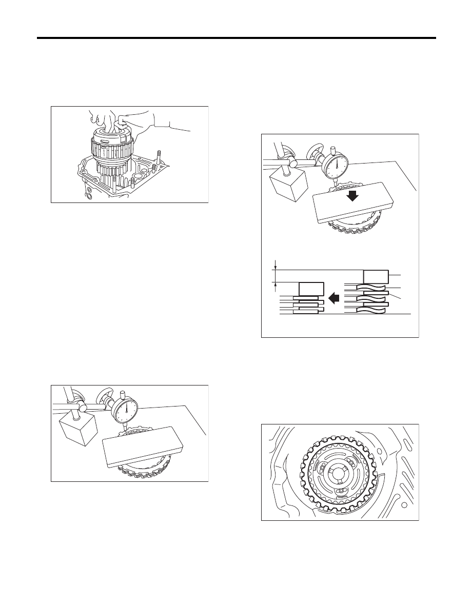
22) Install the planetary gear and low clutch as-
sembly to the transmission case.
NOTE:
When installing the low clutch and planetary gear
assembly while rotating them, rotate them slowly
and pay attention not to damage the seal ring.
23) Measure the amount of drive plate compres-
sion and record that value.
(1) Place the dish plate, driven plate, drive plate
and retaining plate neatly in this order on sur-
face table.
(2) Set the dial gauge to retaining plate, and
read its scale.
NOTE:
The value, which is read in the gauge at this time, is
zero point.
(3) Scale and record the weight “Z” of the flat
board that will be placed on the retaining plate.
NOTE:
• Use a stiff board which does not bend against
load as a flat board to be put on retaining plate.
• Use a flat board weighing less than 10.2 kgf
(22.5 lb).
(4) Put the flat board on retaining plate.
(5) Using the following formula, read the push/
pull gauge, and calculate “N”.
N = 100 N (10.2 kgf, 22.5 lb) – Z
N: Value indicated on push/pull gauge
100 N (10.2 kgf, 22.5 lb) : Load applied to clutch
plate
Z: Flat board weight
(6) Press the center of retaining plate with a
force of N using a push/pull gauge, and mea-
sure and record height “A”. Measure at three or
more locations spaced by equal distances and
take the average value.
NOTE:
If measuring in three locations, measure every
120°. If measuring in four locations, measure every
90°.
24) Install pressure plate, drive plate of 2-4 brake,
driven plate, retaining plate, and snap ring.
AT-00255
AT-01720
A Measured value
(A) Driven plate
(B) Drive plate
(C) Retaining plate
AT-01723
(C)
(B)
(A)
A
AT-00254
4AT-109
AT Main Case
AUTOMATIC TRANSMISSION
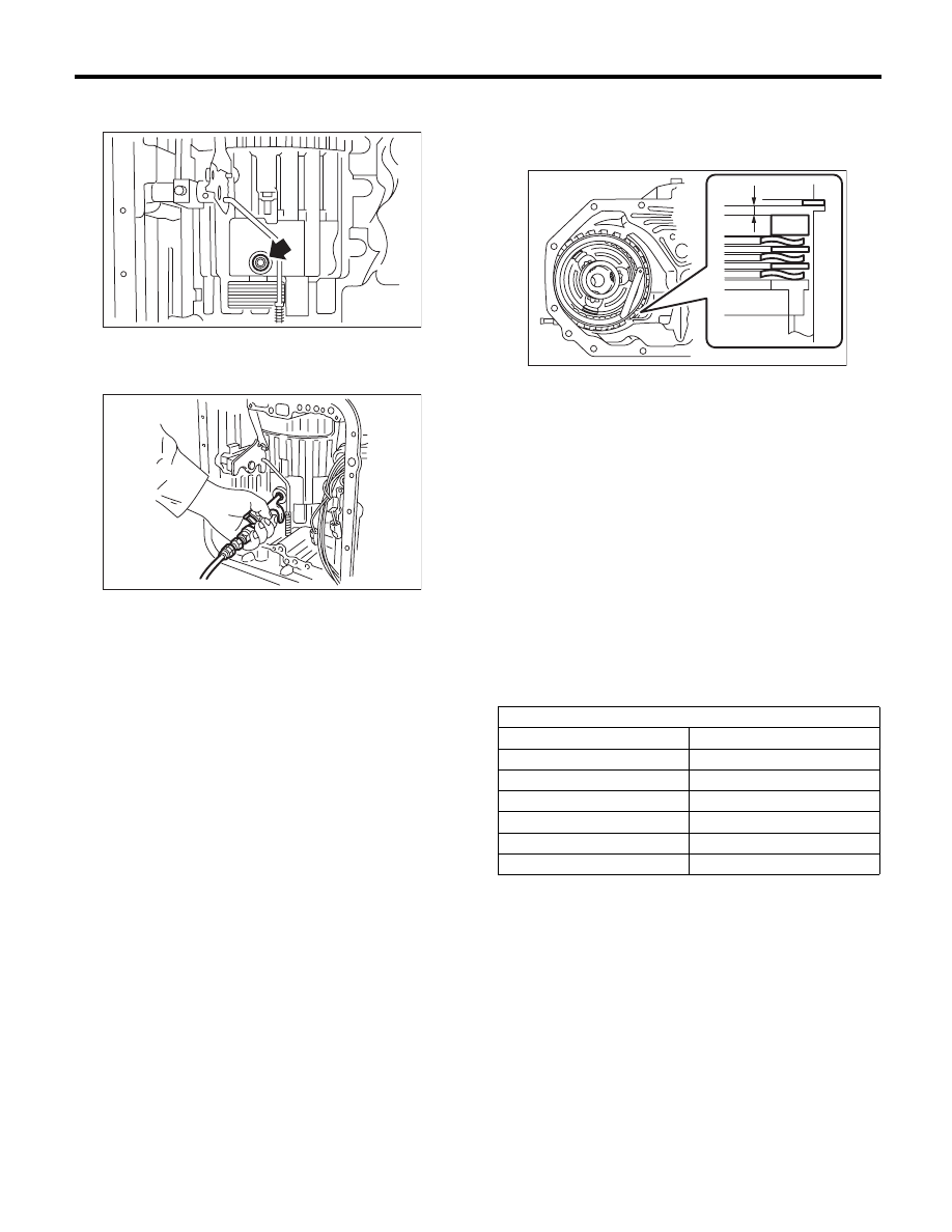
25) Install a new 2-4 brake oil seal to the transmis-
sion case.
26) After all 2-4 brake component parts have been
installed, blow in air intermittently and confirm the
operation of the brake.
27) Check the piston stroke.
(1) Measure clearance “B” between the retain-
ing plate and snap ring. At this time, do not
press down the retaining plate.
(2) Piston stroke calculation
Calculate with A and B dimensions recorded
before. If the calculated value exceeds the ser-
vice limit, replace the drive plate with a new part
and adjust it within the initial specification.
T = A + B
T: Piston stroke
A: Amount of drive plate compression
B: Clearance between retaining plate and snap
ring
Initial standard:
1.7 — 2.1 mm (0.067 — 0.083 in)
Limit thickness:
2.3 mm (0.091 in)
AT-04848
AT-00290
B Measured value
Retaining plate
Part No.
Thickness mm (in)
31567AA991
5.6 (0.220)
31567AB001
5.8 (0.228)
31567AB011
6.0 (0.236)
31567AB021
6.2 (0.244)
31567AB031
6.4 (0.252)
31567AB041
6.6 (0.260)
AT-01724
B
4AT-110
AT Main Case
AUTOMATIC TRANSMISSION
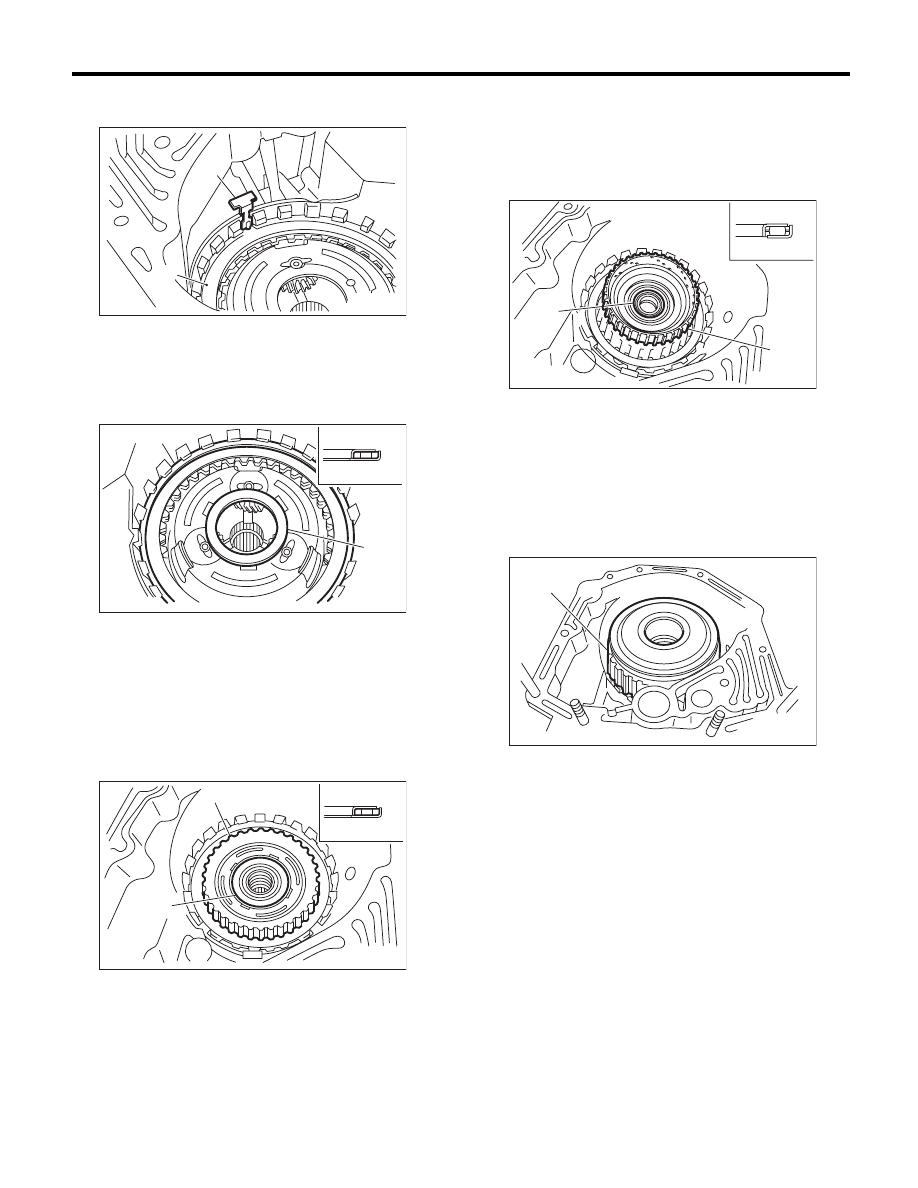
28) Be careful not to mistake the location of the leaf
spring to be installed.
29) Install the thrust needle bearing in the correct
direction.
30) Install the front sun gear and the thrust needle
bearing.
31) Apply vaseline, and attach the thrust needle
bearing to the high clutch hub, then engage the
splines of the front planetary carrier correctly to in-
stall the high clutch hub.
32) Install the thrust needle bearing in the correct
direction.
33) Install the high clutch assembly and reverse
clutch assembly.
34) Adjust the total end play. <Ref. to 4AT-88, AD-
JUSTMENT, Oil Pump Housing.>
(A) Leaf spring
(B) Retaining plate
(A) Snap ring
(B) Thrust needle bearing
(C) Upside
(D) Downside
(E) Outside
(A) Front sun gear
(B) Thrust needle bearing
(C) Upside
(D) Downside
(E) Outside
AT-00252
(A)
(B)
AT-02217
(A)
(B)
(C)
(D)
(E)
AT-02218
(A)
(B)
(C)
(D)
(E)
(A) High clutch hub
(B) Thrust needle bearing
(C) Upside
(D) Downside
(E) Outside
(A) High clutch and reverse clutch ASSY
AT-02219
(C)
(D)
(E)
(A)
(B)
AT-00235
(A)
4AT-111
AT Main Case
AUTOMATIC TRANSMISSION
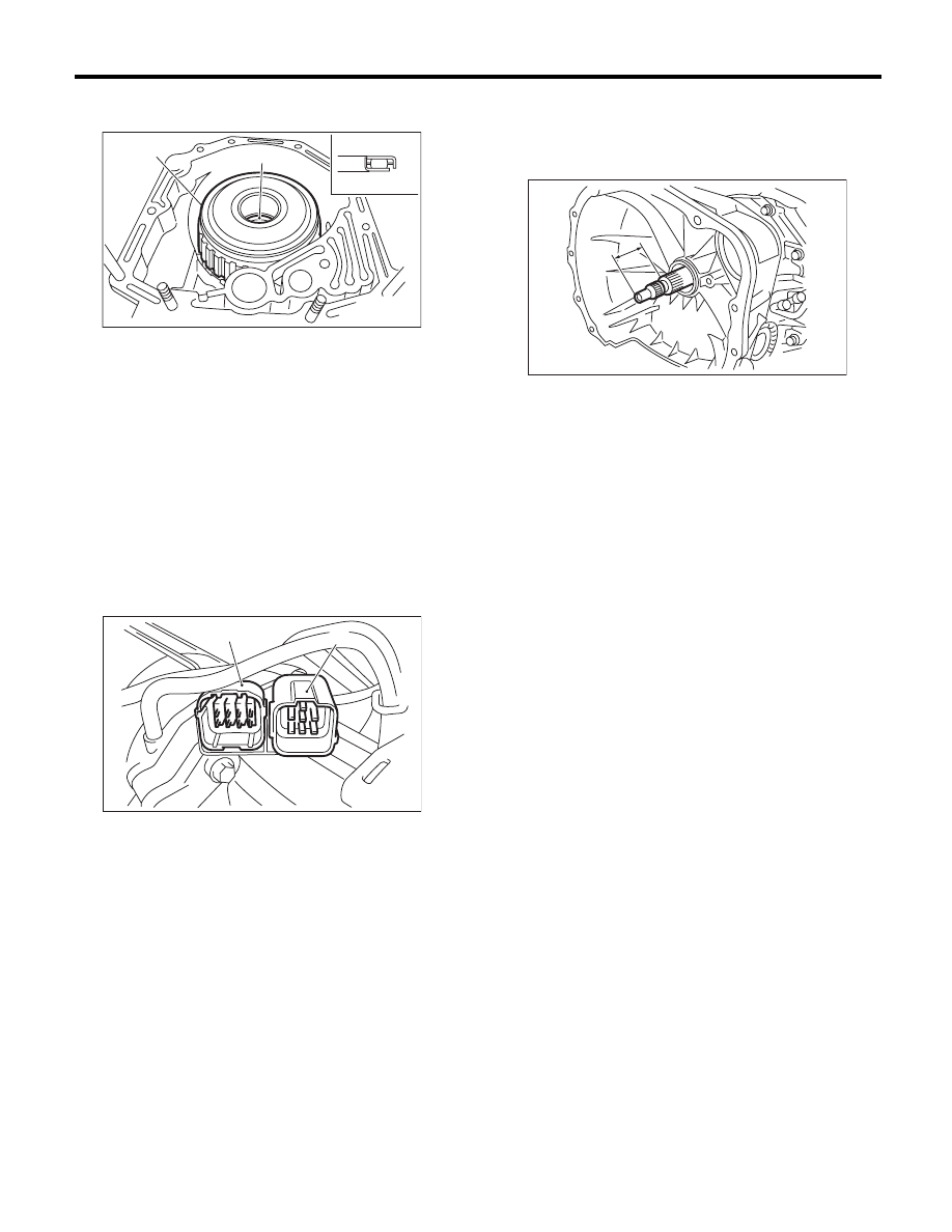
35) Install the thrust needle bearing in the correct
direction.
36) Install a new gasket along with the oil pump
housing assembly. <Ref. to 4AT-84, INSTALLA-
TION, Oil Pump Housing.>
37) Install the converter case to the transmission
case assembly. <Ref. to 4AT-81, INSTALLATION,
Converter Case.>
38) Insert the inhibitor switch connector and trans-
mission harness connector onto the stay.
39) Install the air breather hose. <Ref. to 4AT-65,
INSTALLATION, Air Breather Hose.>
40) Install the ATF cooler pipe. <Ref. to 4AT-63, IN-
STALLATION, ATF Cooler Pipe and Hose.>
41) Install the oil charge pipe together with an O-
ring. <Ref. to 4AT-66, INSTALLATION, Oil Charge
Pipe.>
42) Insert the input shaft while rotating it lightly by
hand, and then check the amount of protrusion.
Normal protrusion A:
50 — 55 mm (1.97 — 2.17 in)
43) Install the torque converter clutch assembly.
<Ref. to 4AT-67, INSTALLATION, Torque Convert-
er Clutch Assembly.>
44) Install the transmission assembly to the vehi-
cle. <Ref. to 4AT-38, INSTALLATION, Automatic
Transmission Assembly.>
(A) High clutch and reverse clutch ASSY
(B) Thrust needle bearing
(C) Upside
(D) Downside
(E) Outside
(A) Transmission harness connectors
(B) Inhibitor switch connector
AT-02220
(A)
(B)
(C)
(D)
(E)
AT-01351
(B)
(A)
A Measured value
AT-03204
A
Нет комментариевНе стесняйтесь поделиться с нами вашим ценным мнением.
Текст