Subaru Legacy IV (2008 year). Service manual — part 363
EN(H4DOTC)(diag)-273
Diagnostic Procedure with Diagnostic Trouble Code (DTC)
ENGINE (DIAGNOSTICS)
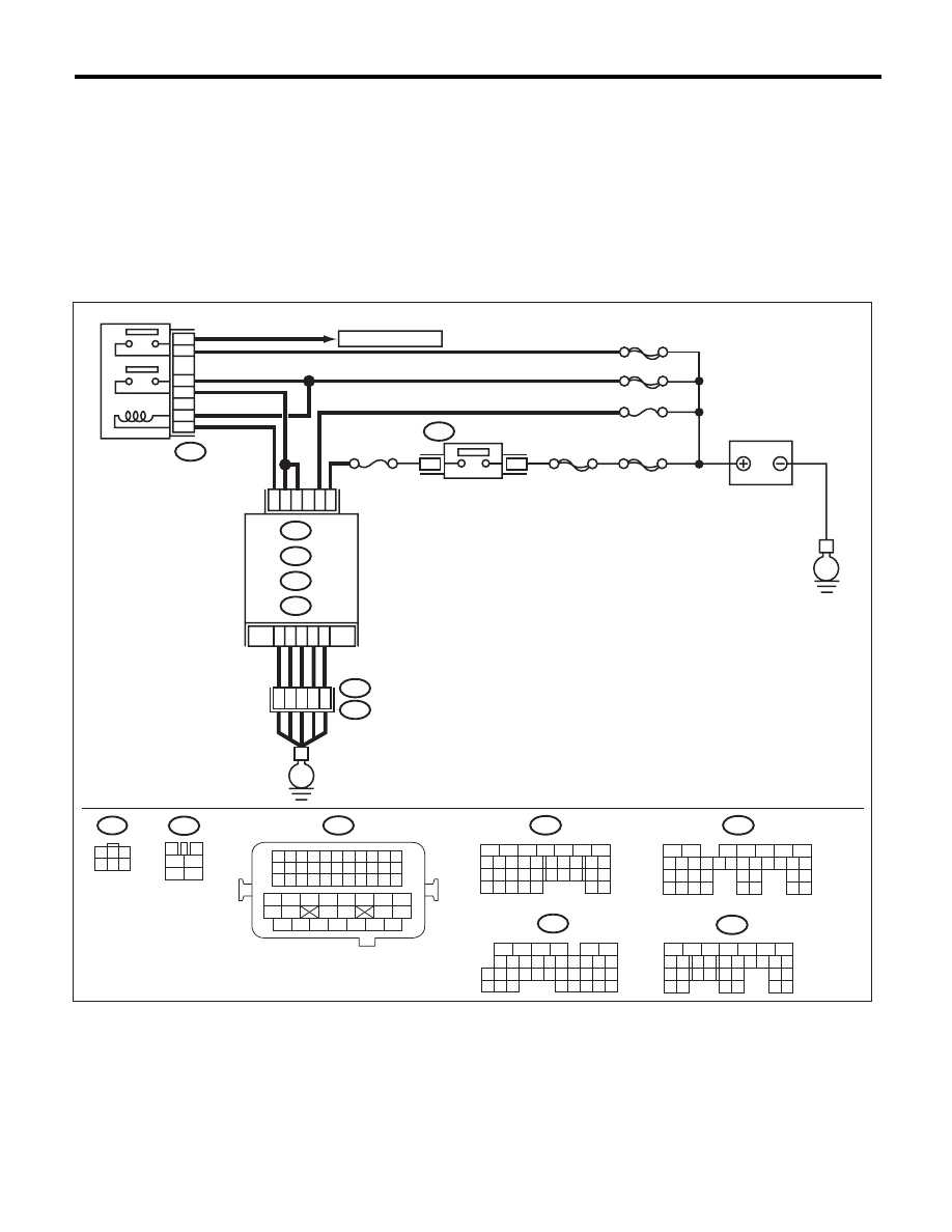
CW:DTC P1560 BACK-UP VOLTAGE CIRCUIT MALFUNCTION
DTC DETECTING CONDITION:
• Immediately at fault recognition
• GENERAL DESCRIPTION <Ref. to GD(H4DOTC)-183, DTC P1560 BACK-UP VOLTAGE CIRCUIT MAL-
FUNCTION, Diagnostic Trouble Code (DTC) Detecting Criteria.>
CAUTION:
After repair or replacement of faulty parts, perform Clear Memory Mode <Ref. to EN(H4DOTC)(diag)-
52, OPERATION, Clear Memory Mode.>, and Inspection Mode <Ref. to EN(H4DOTC)(diag)-43, PRO-
CEDURE, Inspection Mode.>.
WIRING DIAGRAM:
EN-05666
16
10 11 12 13 14 15
25
24
30
9
8
7
17 18 19 20
28
21 22 23
29
32
31
1
2
3
4
5
6
27
26
33 34 35
B136
C:
SBF-6
MAIN SBF
SBF-7
B72
A7
B2
C23
D2
A5
D3
B5
B19
No.12
B47
E2
B21
1
2
4
6
5
3
E
E
B134
B135
A:
C: B136
D: B137
B:
35
34
40
3
4
1
2
5
6
B47
No.13
D7
36
B134
5
6
7
8
2
1
9
4
3
10
24
22 23
25
11 12 13 14 15
26 27
28
16 17
18 19 20 21
33 34
29
32
30 31
B135
5
6
7
8
2
1
9
4
3
10
24
22 23
25
11 12 13 14 15
26 27
28
16 17 18 19
20 21
29 30 31
32 33
34 35
B137
5
6
7
8
2
1
9
4
3
10
22 23
11 12 13 14 15
24 25
26
16 17
18 19 20 21
27
28 29
30 31
B21
1 2 3 4
12 13 14 15
5 6 7 8
16 17 18 19
9 10 11
20 21 22
23 24 25 26 27 28 29 30 31 32 33
35
34
37
36
39
38
41
40
43
42
44
45
47
46
49
48
51
50
53
52
54
B72
1
3
4 5 6
2
A:
B:
D:
SBF-5
D1
37
3
1
MAIN RELAY
TO OXYGEN SENSOR
IGNITION
SWITCH
BATTERY
ECM

EN(H4DOTC)(diag)-274
Diagnostic Procedure with Diagnostic Trouble Code (DTC)
ENGINE (DIAGNOSTICS)
Step
Check
Yes
No
1
CHECK INPUT SIGNAL OF ECM.
1) Turn the ignition switch to OFF.
2) Measure the voltage between ECM and
chassis ground.
Connector & terminal
(B135) No. 5 (+) — Chassis ground (–):
Is the voltage 10 V or more?
Repair the poor
contact of ECM
connector.
Go to step 2.
2
CHECK HARNESS BETWEEN ECM AND
MAIN FUSE BOX CONNECTOR.
1) Disconnect the connectors from ECM.
2) Measure the resistance between ECM and
chassis ground.
Connector & terminal
(B135) No. 5 — Chassis ground:
Is the resistance 1 M
: or
more?
Go to step 3.
Repair the ground
short circuit of har-
ness between
ECM and battery
terminal.
3
CHECK FUSE NO. 13.
Is the fuse blown out?
Replace the fuse.
Repair the harness
and connector.
NOTE:
In this case, repair
the following item:
• Open circuit in
harness between
ECM and battery
• Poor contact in
ECM connector
• Poor contact of
battery terminal
EN(H4DOTC)(diag)-275
Diagnostic Procedure with Diagnostic Trouble Code (DTC)
ENGINE (DIAGNOSTICS)
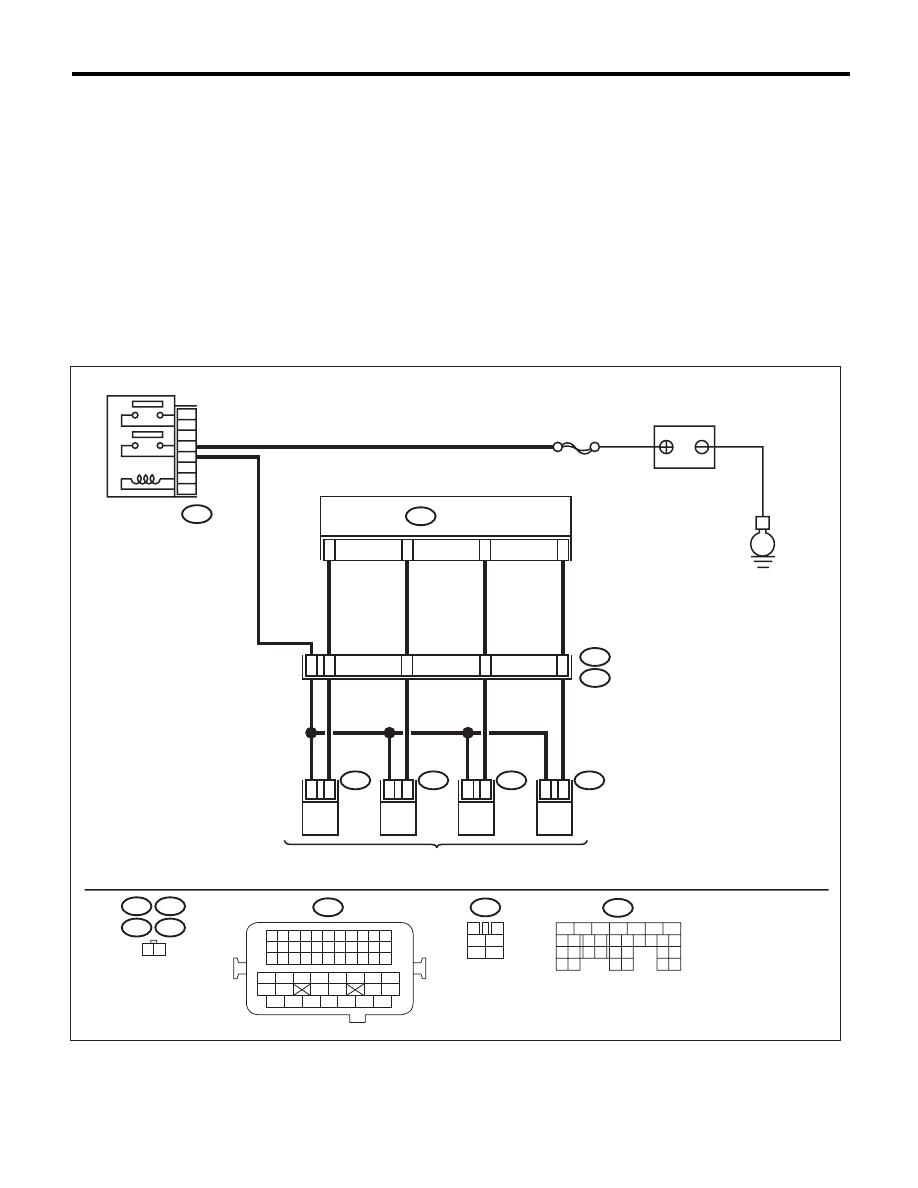
CX:DTC P1602 CONTROL MODULE PROGRAMMING ERROR
DTC DETECTING CONDITION:
• Two consecutive driving cycles with fault
• GENERAL DESCRIPTION <Ref. to GD(H4DOTC)-185, DTC P1602 CONTROL MODULE PROGRAM-
MING ERROR, Diagnostic Trouble Code (DTC) Detecting Criteria.>
TROUBLE SYMPTOM:
• Engine keeps running at higher speed than specified idle speed.
• Engine keeps running at a lower speed than the specified idle speed.
• Engine stalls.
CAUTION:
After repair or replacement of faulty parts, perform Clear Memory Mode <Ref. to EN(H4DOTC)(diag)-
52, OPERATION, Clear Memory Mode.>, and Inspection Mode <Ref. to EN(H4DOTC)(diag)-43, PRO-
CEDURE, Inspection Mode.>.
WIRING DIAGRAM:
EN-05668
E
#4
1
2
SBF-7
#3
1
2
#2
1
2
B21
#1
1
2
48
54
53
52
51
8
9
10
11
1 2
5
3
6
4
2
1
B21
B137
E5
E5
E2
E6
E6
E16
E16
E17
B47
E17
B47
3
4
1
2
5
6
B137
1 2 3 4
12 13 14 15
5 6 7 8
16 17 18 19
9 10 11
20 21 22
23 24 25 26 27 28 29 30 31 32 33
35
34
37
36
39
38
41
40
43
42
44
45
47
46
49
48
51
50
53
52
54
5
6
7
8
2
1
9
4
3
10
22 23
11 12 13 14 15
24 25
26
16 17
18 19 20 21
27
28 29
30 31
MAIN RELAY
ECM
BATTERY
FUEL INJECTOR
EN(H4DOTC)(diag)-276
Diagnostic Procedure with Diagnostic Trouble Code (DTC)
ENGINE (DIAGNOSTICS)
EN-05673
5
6
7
8
2
1
9
4
3
10
24
22 23
25
11 12 13 14 15
26 27
28
16 17
18 19 20 21
33 34
29
32
30 31
1 2
7 8
3
4
5
6
1 2 3 4 5 6 7 8 9 10 11
12 13 14 15 16 17 18 19 20 21 22
23 24 25
34 35
36 37 38 39 40 41
48 49
50 51 52 53 54
42 43
44 45
46 47
26 27 28 29 30 31 32 33
1 2 3 4
5 6 7 8
1
2
7
8 9
5
6
3
4
10 11 12
19 20 21
29
30 31
13 14 15 16 17
27
28
18
22 23
24 25
26
1
2
8 9
5
6
3
4
10 11 12
19 20 21
29 30
31
13 14 15 16
17
27
28
18
22 23 24 25 26
7
32 33 34 35
1 2 3 4 5 6
E57
B47
B137
D:
B21
B122
B136
C:
B362
B134
A:
36
40
34
35
37
E2
B21
C21
C1
A29
6
A18
C6
A28
6
4
25
*
*
B122
24
E
38
39
28
D5
D4
A19
A5
D7
D1
D2
D3
3
E57
2
1
5
B134
B362
B47
5
7
6
A:
B137
B136
D:
C:
*
E
SBF-7
8
6
4
E
3
4
1
2
5
6
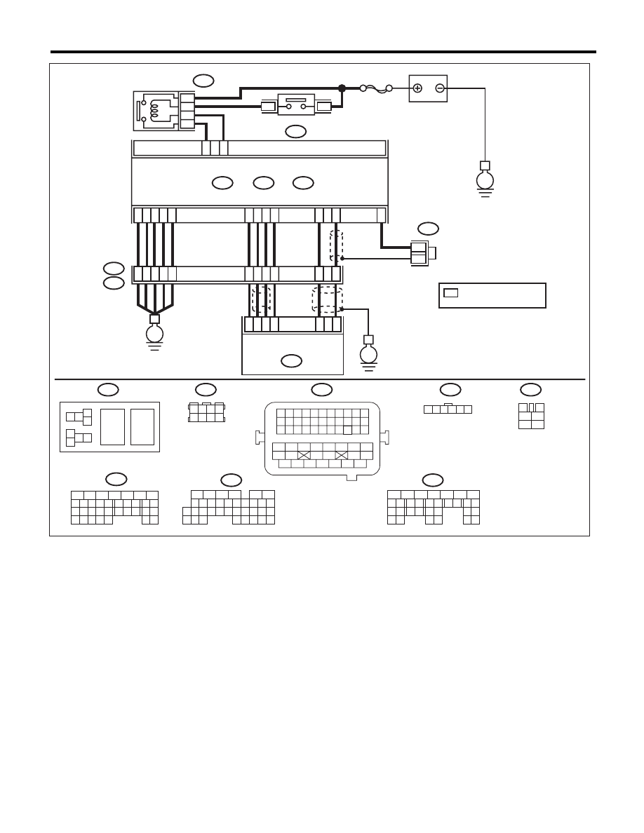
ELECTRONIC
THROTTLE
CONTROL RELAY
MAIN RELAY
BATTERY
ECM
ELECTRONIC THROTTLE
CONTROL
: TERMINAL No. OPTIONAL
ARRANGEMENT
Нет комментариевНе стесняйтесь поделиться с нами вашим ценным мнением.
Текст