Subaru Legacy IV (2008 year). Service manual — part 362
EN(H4DOTC)(diag)-269
Diagnostic Procedure with Diagnostic Trouble Code (DTC)
ENGINE (DIAGNOSTICS)
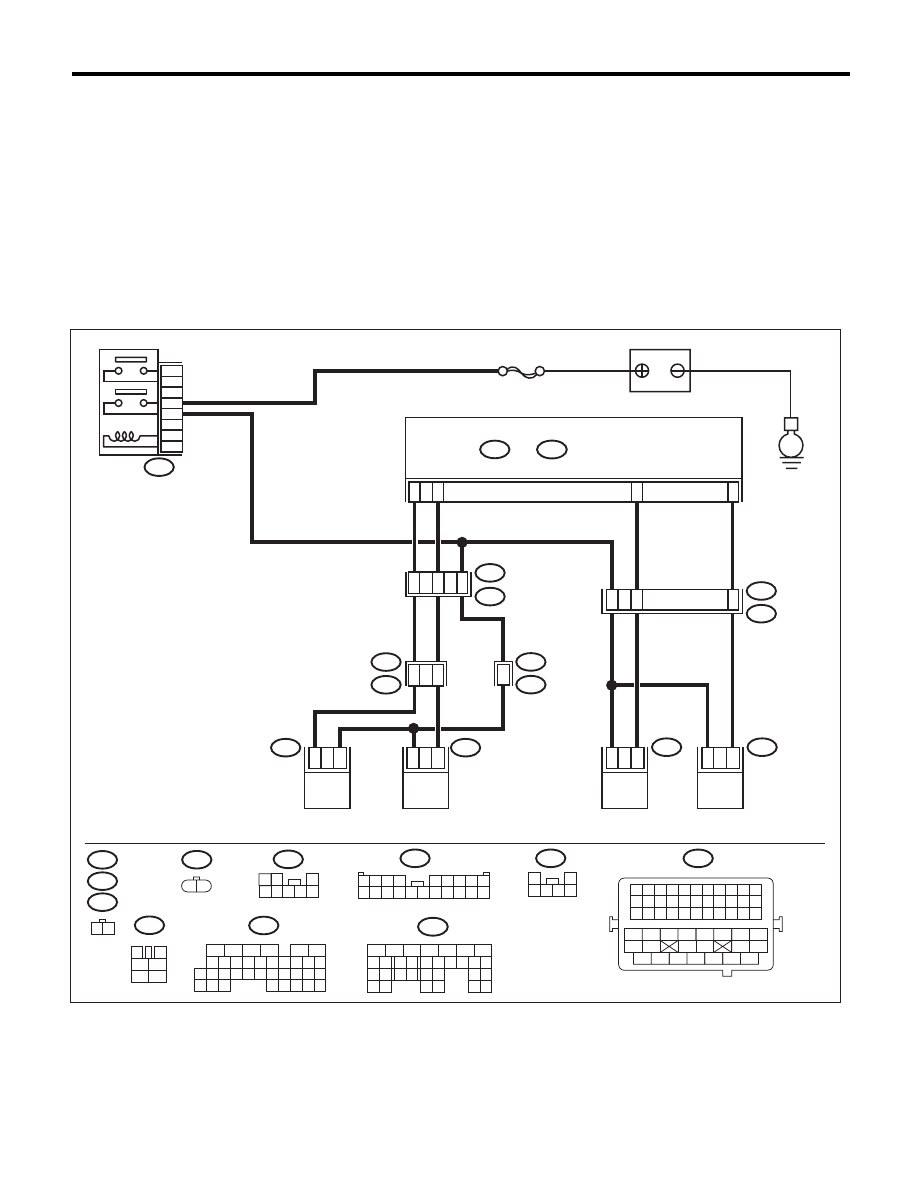
CU:DTC P1443 VENT CONTROL SOLENOID VALVE FUNCTION PROBLEM
DTC DETECTING CONDITION:
• Immediately at fault recognition
• GENERAL DESCRIPTION <Ref. to GD(H4DOTC)-179, DTC P1443 VENT CONTROL SOLENOID
VALVE FUNCTION PROBLEM, Diagnostic Trouble Code (DTC) Detecting Criteria.>
TROUBLE SYMPTOM:
Improper fuel supply
CAUTION:
After repair or replacement of faulty parts, perform Clear Memory Mode <Ref. to EN(H4DOTC)(diag)-
52, OPERATION, Clear Memory Mode.>, and Inspection Mode <Ref. to EN(H4DOTC)(diag)-43, PRO-
CEDURE, Inspection Mode.>.
WIRING DIAGRAM:
EN-05679
SBF-7
E4
B47
E
5
3
6
4
2
1
2
1
C17
C28
D29
C7
R15
R213
R68
R144
R1
B97
14
15
2
2
1
1
7
1
5
E52
2
1
E52
R144
E4
B47
R67
B97
R213
R68
1 2
3
4
1
2
5
6
B21
1 2
1 2
3
4 5 6 7 8
1 2 3 4 5 6 7 8 9 10 11
12 13 14 15 16 17 18 19 20 21 22
23 24 25 26 27 28 29 30 31 32 33
34
35
42
43
36
37
38
39
48
49
50
51
52
53
54
40
41
44
45
46
47
1
2
3 4 5 6
1 2 3 4
5 6 7 8 9
10 11 12 13 14 15 16 17 18 19 20
R46
R67
6
B21
E2
11
48
16
10 11 12 13 14 15
25
24
30
9
8
7
17 18 19 20
28
21 22 23
29
32
31
1
2
3
4
5
6
27
26
33 34 35
B136
C:
B137
5
6
7
8
2
1
9
4
3
10
22 23
11 12 13 14 15
24 25
26
16 17
18 19 20 21
27
28 29
30 31
D:
B136
C:
B137
D:
44
MAIN RELAY
ECM
BATTERY
DRAIN VALVE
PRESSURE
CONTROL
SOLENOID VALVE
PURGE CONTROL
SOLENOID VALVE 1
PURGE CONTROL
SOLENOID VALVE 2
EN(H4DOTC)(diag)-270
Diagnostic Procedure with Diagnostic Trouble Code (DTC)
ENGINE (DIAGNOSTICS)
Step
Check
Yes
No
1
CHECK FOR ANY OTHER DTC ON DISPLAY. Is any other DTC displayed?
Check the appro-
priate DTC using
the “List of Diag-
nostic Trouble
Code (DTC)”.
<Ref. to
EN(H4DOTC)(diag)
-81, List of Diag-
nostic Trouble
Code (DTC).>
Go to step 2.
2
CHECK DRAIN HOSE.
Check the drain hose for clogging.
Is there clogging in the drain
hose?
Replace the drain
hose.
Go to step 3.
3
CHECK DRAIN VALVE OPERATION.
1) Turn the ignition switch to OFF.
2) Connect the delivery (test) mode connector
at the lower portion of instrument panel (on the
driver’s side).
3) Turn the ignition switch to ON.
4) Operate the drain valve.
NOTE:
Drain valve can be operated using the Subaru
Select Monitor. For the procedures, refer to
“Compulsory Valve Operation Check Mode”.
<Ref. to EN(H4DOTC)(diag)-53, Compulsory
Valve Operation Check Mode.>
Does the drain valve operate?
Repair the poor
contact of ECM
connector.
Replace the drain
valve. <Ref. to
EC(H4DOTC)-19,
Drain Valve.>
EN(H4DOTC)(diag)-271
Diagnostic Procedure with Diagnostic Trouble Code (DTC)
ENGINE (DIAGNOSTICS)
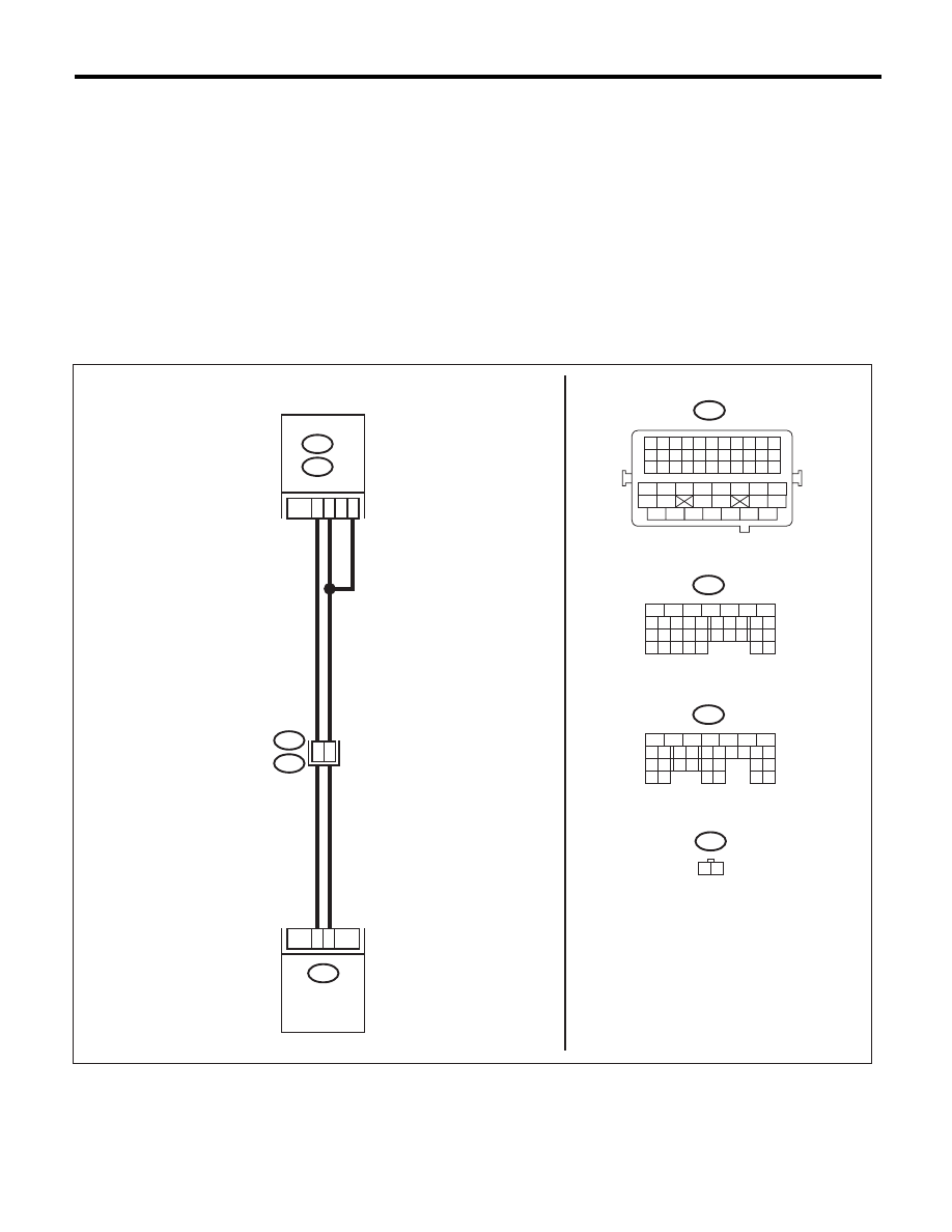
CV:DTC P1491 POSITIVE CRANKCASE VENTILATION (BLOW-BY) FUNCTION
PROBLEM
DTC DETECTING CONDITION:
• Immediately at fault recognition
• GENERAL DESCRIPTION <Ref. to GD(H4DOTC)-181, DTC P1491 POSITIVE CRANKCASE VENTILA-
TION (BLOW-BY) FUNCTION PROBLEM, Diagnostic Trouble Code (DTC) Detecting Criteria.>
TROUBLE SYMPTOM:
Improper idling
CAUTION:
After repair or replacement of faulty parts, perform Clear Memory Mode <Ref. to EN(H4DOTC)(diag)-
52, OPERATION, Clear Memory Mode.>, and Inspection Mode <Ref. to EN(H4DOTC)(diag)-43, PRO-
CEDURE, Inspection Mode.>.
WIRING DIAGRAM:
EN-05683
E80
1
2
A30
D6
D26
45
41
B21
E2
B137
D:
B134
A:
D:
A:
B137
B134
B21
E80
1 2
5
6
7
8
2
1
9
4
3
10
22 23
11 12 13 14 15
24 25
26
16 17
18 19 20 21
27
28 29
30 31
1 2 3 4 5 6 7 8 9 10 11
12 13 14 15 16 17 18 19 20 21 22
23 24 25 26 27 28 29 30 31 32 33
34
35
42
43
36
37
38
39
48
49
50
51
52
53
54
40
41
44
45
46
47
8
5
6
10 11 12 13 14 15
7
2
1
3
4
16
30
19 20
22
28 29
9
17
18
25
21
23 24
32
31
26 27
33 34
ECM
PCV HOSE
ASSY

EN(H4DOTC)(diag)-272
Diagnostic Procedure with Diagnostic Trouble Code (DTC)
ENGINE (DIAGNOSTICS)
Step
Check
Yes
No
1
CHECK BLOW-BY HOSE.
Check the condition of the blow-by hose.
Is there any disconnection or
crack in blow-by hose?
Repair or replace
the blow-by hose.
Go to step 2.
2
CHECK HARNESS BETWEEN ECM AND
PCV HOSE ASSEMBLY.
1) Turn the ignition switch to OFF.
2) Disconnect the connectors from the ECM
and PCV hose assembly.
3) Measure the resistance of harness between
ECM and PCV hose assembly.
Connector & terminal
(B134) No. 30 — (E80) No. 2:
Is the resistance less than 1
:? Go to step 3.
Repair the harness
and connector.
NOTE:
In this case, repair
the following item:
• Open circuit in
harness between
ECM and PCV
hose assembly
• Poor contact of
coupling connector
3
CHECK HARNESS BETWEEN ECM AND
PCV HOSE ASSEMBLY.
Measure the resistance between PCV hose
assembly and chassis ground.
Connector & terminal
(B134) No. 30 — Chassis ground:
Is the resistance 1 M
: or
more?
Go to step 4.
Repair the ground
short circuit of har-
ness between
ECM and PCV
hose assembly.
4
CHECK GROUND CIRCUIT OF PCV HOSE
ASSEMBLY.
Measure the resistance of harness between
PCV hose assembly and engine ground.
Connector & terminal
(E80) No. 1 — Engine ground:
Is the resistance less than 5
:? Go to step 5.
Repair the open
circuit of harness
between PCV hose
assembly and
engine ground.
5
CHECK THE PCV HOSE ASSEMBLY.
Measure the resistance between the PCV hose
assembly terminals.
Terminals
No. 1 — No. 2:
Is the resistance less than 1
:? Repair the poor
contact in ECM
and PCV hose
assembly connec-
tor.
Replace the PCV
hose assembly.
Нет комментариевНе стесняйтесь поделиться с нами вашим ценным мнением.
Текст