Subaru Legacy IV (2008 year). Service manual — part 745
5AT-104
AT Main Case
AUTOMATIC TRANSMISSION
18) Install the thrust needle bearing of middle carri-
er assembly.
19) Measure the total end play, and select the
bearing. <Ref. to 5AT-107, ADJUSTMENT, AT
Main Case.>
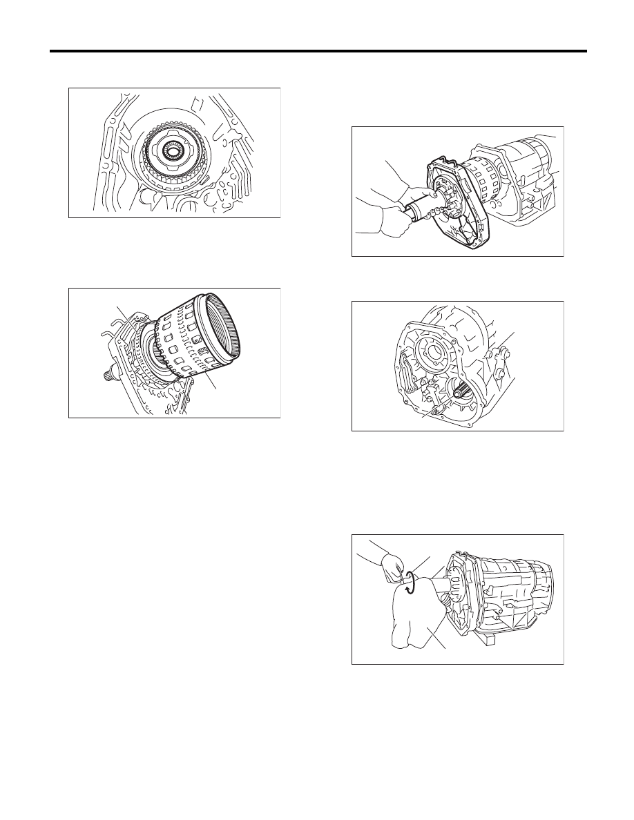
20) Install the impact clutch pack assembly to oil
pump cover.
21) Turn the transmission sideways.
22) Install the oil pump cover.
(1) Apply ATF to the O-ring of input clutch shaft.
(2) Install the oil pump cover to AT main case
while supporting the input clutch shaft and oil
pump housing with your hand.
(3) Make sure the rear end of drive pinion shaft
is engaged to the spline of reduction driven
gear.
(4) Protect the input clutch shaft with a cloth,
and rotate to engage the spline of the input
clutch and rear carrier using pliers.
NOTE:
Work with pressing the oil pump cover.
(A) Impact clutch pack ASSY
(B) Front sun gear ASSY
AT-01991
AT-02006
(A)
(B)
(A) Drive pinion shaft
(A) Cloth
AT-01990
AT-02092
(A)
AT-02046
(A)
5AT-105
AT Main Case
AUTOMATIC TRANSMISSION
(5) Combine the oil pump cover with transmis-
sion main case.
Tightening torque:
41 N·m (4.2 kgf-m, 30.2 ft-lb)
23) Install the center differential carrier. <Ref. to
5AT-77, INSTALLATION, Center Differential Carri-
er.>
24) Install the reduction driven gear. <Ref. to 5AT-
74, INSTALLATION, Reduction Driven Gear.>
25) Install the extension case. <Ref. to 5AT-68, IN-
STALLATION, Extension Case.>
26) Install the control valve body. <Ref. to 5AT-58,
INSTALLATION, Control Valve Body.>
27) Install the converter case assembly to the
transmission case assembly. <Ref. to 5AT-81, IN-
STALLATION, Converter Case.>
28) Install the air breather hose. <Ref. to 5AT-65,
INSTALLATION, Air Breather Hose.>
29) Install the ATF cooler pipe. <Ref. to 5AT-63, IN-
STALLATION, ATF Cooler Pipe and Hose.>
30) Install the oil charge pipe together with an O-
ring. <Ref. to 5AT-66, INSTALLATION, Oil Charge
Pipe.>
31) Install the torque converter assembly. <Ref. to
5AT-67, INSTALLATION, Torque Converter As-
sembly.>
32) Install the transmission assembly to the vehi-
cle. <Ref. to 5AT-43, INSTALLATION, Automatic
Transmission Assembly.>
33) Perform Clear Memory 2 operation. <Ref. to
5AT(diag)-20, CLEAR MEMORY MODE, OPERA-
TION, Subaru Select Monitor.>
34) Execute the learning control promotion. <Ref.
to 5AT(diag)-24, PROCEDURE, Learning Con-
trol.>
35) Perform the inspection at the end of repair
work, and make sure there is no faulty as below;
• Excessive shift shock
• Oil leakage from the transmission body, etc.
• Occurrence of noise caused by interference etc.
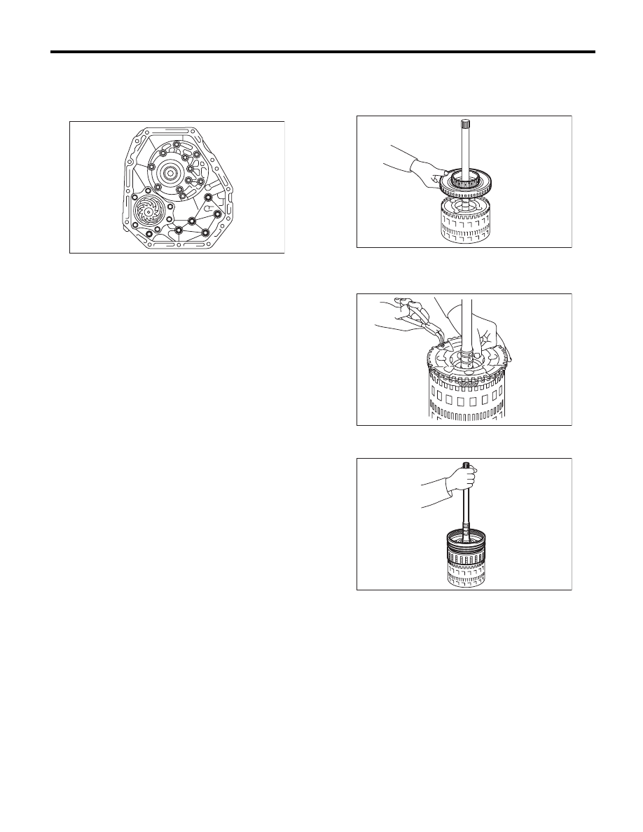
C: DISASSEMBLY
1. INPUT CLUTCH PACK ASSEMBLY
1) Remove the front sun gear.
2) Remove the thrust bearing.
3) Remove the snap ring, and then remove the
front carrier.
4) Remove the input clutch assembly from rear in-
ternal gear.
AT-01976
AT-02007
AT-02008
AT-02009
5AT-106
AT Main Case
AUTOMATIC TRANSMISSION
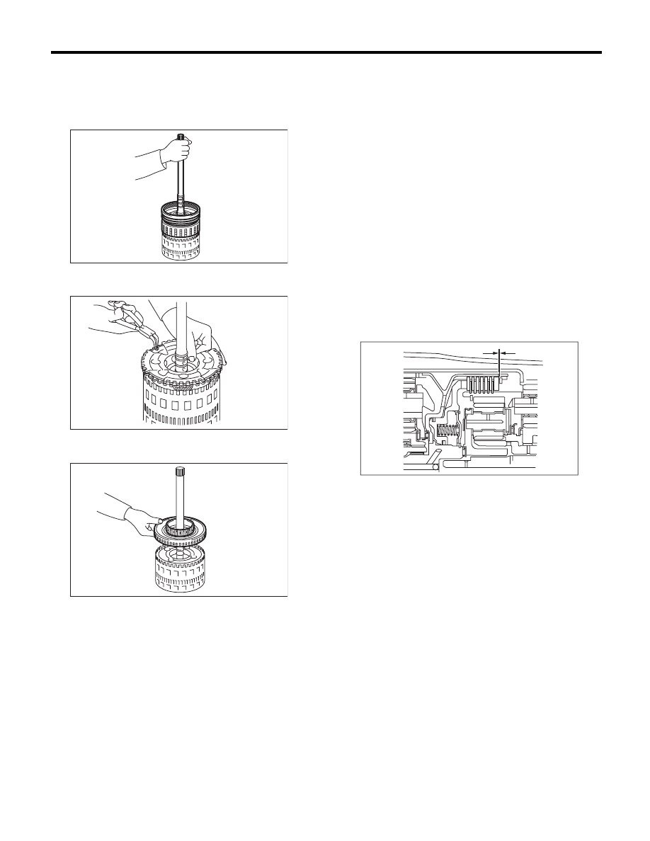
D: ASSEMBLY
1. INPUT CLUTCH PACK ASSEMBLY
1) Assemble the input clutch assembly to rear inter-
nal gear.
2) Install the front carrier, and then install the snap
ring.
3) Install the thrust bearing.
4) Install the front sun gear.
E: INSPECTION
1. FRONT, MIDDLE & REAR PLANETARY
CARRIER ASSEMBLY
Check the following items.
• Visually inspect the tooth surface of planetary
gear, and replace with new part if damaged, broken
or excessively worn.
• Inspect the planetary carrier body for damage or
breakage.
2. INPUT CLUTCH
• Check the clearance of the input clutch. Measure
the clearance “L” between snap ring and retaining
plate using a thickness gauge. If it is out of specifi-
cation, replace the entire direct clutch assembly.
• Check for damage on the drive plate, driven
plate and snap ring, and replace the entire input
clutch assembly if damaged.
Standard:
0.7 — 1.1 mm (0.028 — 0.043 in)
AT-02009
AT-02008
AT-02007
L Measured value
AT-03259
L
5AT-107
AT Main Case
AUTOMATIC TRANSMISSION
3. HIGH & LOW REVERSE CLUTCH
ASSEMBLY
• Check the clearance of the high & low reverse
clutch.
Measure the clearance “L” between snap ring and
retaining plate using a thickness gauge. If it is out of
specification, replace the entire high & low reverse
clutch assembly.
• Check for damage on the drive plate, driven
plate and snap ring, and replace the entire high &
low reverse clutch assembly if damaged.
Standard:
1.8 — 2.2 mm (0.071 — 0.087 in)
4. DIRECT CLUTCH ASSEMBLY
• Check the clearance of direct clutch.
Measure the clearance “L” between snap ring and
retaining plate using a thickness gauge. If it is out of
specification, replace them as direct clutch assem-
bly.
• Check for damage on the drive plate, driven
plate and snap ring, and replace the entire direct
clutch assembly if damaged.
Standard:
0.6 — 1.0 mm (0.024 — 0.039 in)
5. REVERSE BRAKE
Check the following items.
• Drive plate facing for wear or damage
• Snap ring for wear, return spring for breakage,
and spring retainer for deformation
• Lip seal and D-ring for damage
• Piston operation
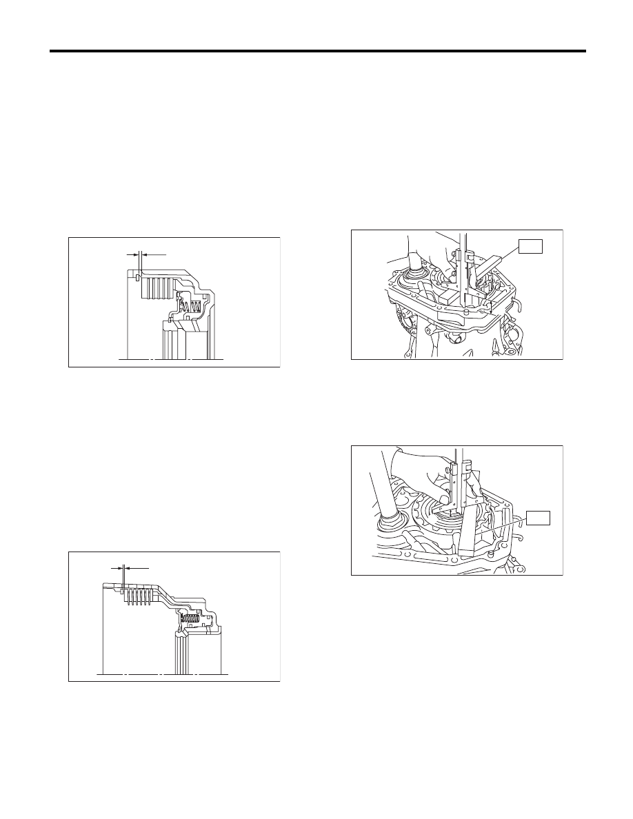
F: ADJUSTMENT
1) Using the ST, measure the height “A” from the
AT main case mating surface to convex surface of
oil pump cover.
ST
499575400
GAUGE
2) Using the ST, measure the depth “B” from the
convex surface of oil pump cover to thrust bearing
transferring surface.
ST
499575400
GAUGE
3) Calculate the measured value from step 1) and
2), and then set the calculated value as “C”.
Calculation formula: C = A – B
L Measured value
L Measured value
AT-02010
L
AT-02011
L
A Measured value
B Measured value
AT-02012
ST
A
AT-02013
ST
B
Нет комментариевНе стесняйтесь поделиться с нами вашим ценным мнением.
Текст