Subaru Legacy IV (2008 year). Service manual — part 342
EN(H4DOTC)(diag)-189
Diagnostic Procedure with Diagnostic Trouble Code (DTC)
ENGINE (DIAGNOSTICS)
BC:DTC P0410 SECONDARY AIR INJECTION SYSTEM
DTC DETECTING CONDITION:
• Two consecutive driving cycles with fault
• GENERAL DESCRIPTION <Ref. to GD(H4DOTC)-94, DTC P0410 SECONDARY AIR INJECTION SYS-
TEM, Diagnostic Trouble Code (DTC) Detecting Criteria.>
CAUTION:
After repair or replacement of faulty parts, perform Clear Memory Mode <Ref. to EN(H4DOTC)(diag)-
52, OPERATION, Clear Memory Mode.>, and Inspection Mode <Ref. to EN(H4DOTC)(diag)-43, PRO-
CEDURE, Inspection Mode.>.
EN(H4DOTC)(diag)-190
Diagnostic Procedure with Diagnostic Trouble Code (DTC)
ENGINE (DIAGNOSTICS)
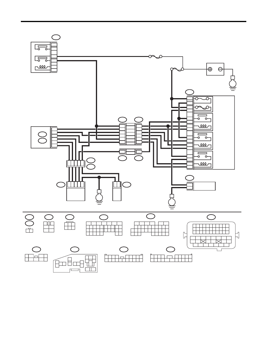
WIRING DIAGRAM:
EN-05678
B47
1
2
4
6
3
5
SBF-7
E
F9
13
12
11
14
1
2
2
1
3
4
16
15
5
6
B143
F37
B144
B21
E2
E41
E40
B134
A:
B136
C:
F37
F11
B21
E40
B47
B144
F9
B143
F37
E41
1 2 3 4
12 13 14 15
5 6 7 8
16 17 18 19
9 10 11
20 21 22
23 24 25 26 27 28 29 30 31 32 33
35
34
37
36
39
38
41
40
43
42
44
45
47
46
49
48
51
50
53
52
54
MAIN
SBF
10A
60A
9
10
8
7
E
E
11
5
20
8
C30
C19
C8
A19
A27
A29
6
1
28
47
3
2
1
6
4
1
2
9
2
16
18
14
12
10
4
14
4
F11
1 2
3
4
1
2
5
6
1
3
4 5 6
2
B134
5
6
7
8
2
1
9
4
3
10
24
22 23
25
11 12 13 14 15
26 27
28
16 17
18 19 20 21
33 34
29
32
30 31
16
10 11 12 13 14 15
25
24
30
9
8
7
17 18 19 20
28
21 22 23
29
32
31
1
2
3
4
5
6
27
26
33 34 35
B136
1
5
7
6
2
8
3
4
9
1 2 3 4
5 6 7 8 9
10 11 12 13 14
15 16 17 18 19 20
1 2 3 4
5 6 7 8 9
10 11 12 13 14 15 16 17 18 19 20
5
6
3
1
2
9
10
12
11
13
14
4
7 8
15
16
46
MAIN RELAY
BATTERY
RELAY HOLDER
SECONDARY
AIR
COMBINATION
VALVE RELAY1
SECONDARY
AIR
COMBINATION
VALVE RELAY2
SECONDARY
AIR PUMP
RELAY
SECONDARY
AIR PUMP
MAIN FUSE
BOX (M/B)
ECM
SECONDARY AIR
COMBINATION VALVE RH
(WITH BUILT-IN PRESSURE SENSOR)
SECONDARY AIR
COMBINATION
VALVE LH

EN(H4DOTC)(diag)-191
Diagnostic Procedure with Diagnostic Trouble Code (DTC)
ENGINE (DIAGNOSTICS)
Step
Check
Yes
No
1
CHECK SECONDARY AIR PUMP FUSE.
Check if the secondary air pump fuse (60 A) is
blown out.
Is the fuse blown out?
Go to step 2.
Go to step 3.
2
CHECK HARNESS BETWEEN FUSE BOX
AND SECONDARY AIR PUMP.
1) Remove the secondary air pump fuse from
the fuse box.
2) Disconnect the secondary air pump con-
nector.
3) Measure resistance between the secondary
air pump fuse and secondary air pump connec-
tor, and chassis ground.
Connector & terminal
(F9) No. 16 — Chassis ground:
(F11) No. 2 — Chassis ground:
Is the resistance 1 M
: or
more?
Replace the fuse
with a new part,
and then connect
the secondary air
pump connector.
Go to step 3.
Repair ground
short of the har-
ness between the
fuse box and the
secondary air
pump.
3
CHECK SECONDARY AIR PUMP OPERA-
TION.
1) Connect the delivery (test) mode connector.
2) Turn the ignition switch to ON.
3) Perform the Clear Memory Mode.
4) Perform operation check for the secondary
air pump using the Subaru Select Monitor.
NOTE:
• Subaru Select Monitor
For detailed operation procedure, refer to
“Clear Memory Mode”<Ref. to
EN(H4DOTC)(diag)-52, Clear Memory Mode.>
and “Compulsory Valve Operation Check
Mode”<Ref. to EN(H4DOTC)(diag)-53, Com-
pulsory Valve Operation Check Mode.>.
• The compulsory operation using the Subaru
Select Monitor is performed only for 5 seconds
in order to protect the secondary air pump.
When operating again, perform the Clear Mem-
ory Mode.
Does the secondary air pump
operate?
Go to step 4.
Go to step 5.
4
CHECK DUCT BETWEEN SECONDARY AIR
PUMP AND COMBINATION VALVE.
Check the duct between the secondary air
pump and combination valve.
Is there damage, clog or dis-
connection of the duct?
Replace, clean or
connect the duct.
Replace the sec-
ondary air combi-
nation valve RH.
<Ref. to
EC(H4DOTC)-22,
Secondary Air
Combination
Valve.>
5
CHECK POWER SUPPLY TO SECONDARY
AIR PUMP.
1) Perform the Clear Memory Mode.
2) Turn the ignition switch to OFF.
3) Disconnect the secondary air pump con-
nector.
4) In the condition of step 3, measure the volt-
age between the secondary air pump connector
and the chassis ground.
NOTE:
For detailed procedure, refer to “Clear Memory
Mode”. <Ref. to EN(H4DOTC)(diag)-52, Clear
Memory Mode.>
Connector & terminal
(F11) No. 2 (+) — Chassis ground (–):
Is the voltage 10 V or more?
Replace the sec-
ondary air pump.
<Ref. to
EC(H4DOTC)-21,
Secondary Air
Pump.>
Go to step 6.

EN(H4DOTC)(diag)-192
Diagnostic Procedure with Diagnostic Trouble Code (DTC)
ENGINE (DIAGNOSTICS)
6
CHECK HARNESS BETWEEN SECONDARY
AIR PUMP RELAY AND SECONDARY AIR
PUMP CONNECTOR.
1) Turn the ignition switch to OFF.
2) Remove the secondary air pump relay.
3) Measure the resistance between the sec-
ondary air pump relay and secondary air pump
connector.
Connector & terminal
(F9) No. 11 — (F11) No. 2:
Is the resistance less than 1
:? Go to step 7.
Repair the open
circuit between
secondary air
pump relay and
secondary air
pump connector.
7
CHECK HARNESS BETWEEN SECONDARY
AIR PUMP CONNECTOR AND CHASSIS
GROUND.
Measure the resistance of the harness between
secondary air pump connector and chassis
ground.
Connector & terminal
(F11) No. 1 — Chassis ground:
Is the resistance less than 5
:? Go to step 8.
Repair the open
circuit of the har-
ness between sec-
ondary air pump
connector and
chassis ground.
8
CHECK SECONDARY AIR PUMP RELAY.
1) Connect the battery to terminals No. 12 and
No. 13 of the secondary air pump relay.
2) Measure the resistance between secondary
air pump relay terminals.
Terminals
No. 14 — No. 11:
Is the resistance less than 1
:? Go to step 9.
Replace the sec-
ondary air pump
relay. <Ref. to
EN(H4DOTC)(diag)
-8, Electrical Com-
ponent Location.>
9
CHECK SECONDARY AIR PUMP RELAY
POWER SOURCE.
1) Turn the ignition switch to ON.
2) Measure the voltage between the second-
ary air pump relay connector and chassis
ground.
Connector & terminal
(F9) No. 14 (+) — Chassis ground (–):
(F9) No. 12 (+) — Chassis ground (–):
Is the voltage 10 V or more?
Go to step 10.
Repair the open or
ground short circuit
of power supply
circuit.
10
CHECK HARNESS BETWEEN ECM AND
SECONDARY AIR PUMP RELAY CONNEC-
TOR.
1) Turn the ignition switch to OFF.
2) Disconnect the connector of ECM.
3) Measure the resistance of harness between
ECM and secondary air pump relay connector.
Connector & terminal
(B136) No. 8 — (F9) No. 13:
Is the resistance less than 1
:? Repair the poor
contact of ECM
connector.
Repair the harness
and connector.
NOTE:
In this case, repair
the following item:
• Open circuit of
harness between
ECM and second-
ary air pump relay
connector.
• Poor contact of
coupling connector
Step
Check
Yes
No
Нет комментариевНе стесняйтесь поделиться с нами вашим ценным мнением.
Текст