Subaru Legacy IV (2008 year). Service manual — part 341
EN(H4DOTC)(diag)-185
Diagnostic Procedure with Diagnostic Trouble Code (DTC)
ENGINE (DIAGNOSTICS)
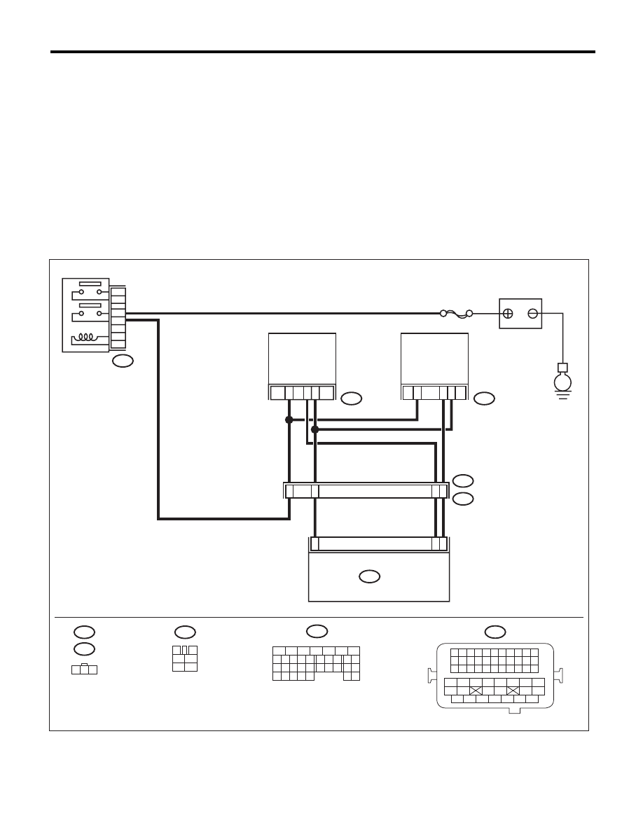
BA:DTC P0340 CAMSHAFT POSITION SENSOR “A” CIRCUIT (BANK 1 OR SINGLE
SENSOR)
DTC DETECTING CONDITION:
• Immediately at fault recognition
• GENERAL DESCRIPTION <Ref. to GD(H4DOTC)-92, DTC P0340 CAMSHAFT POSITION SENSOR “A”
CIRCUIT (BANK 1 OR SINGLE SENSOR), Diagnostic Trouble Code (DTC) Detecting Criteria.>
TROUBLE SYMPTOM:
• Engine stalls.
• Failure of engine to start
CAUTION:
After repair or replacement of faulty parts, perform Clear Memory Mode <Ref. to EN(H4DOTC)(diag)-
52, OPERATION, Clear Memory Mode.>, and Inspection Mode <Ref. to EN(H4DOTC)(diag)-43, PRO-
CEDURE, Inspection Mode.>.
WIRING DIAGRAM:
EN-05677
5
6
7
8
2
1
9
4
3
10
24
22 23
25
11 12 13 14 15
26 27
28
16 17
18 19 20 21
33 34
29
32
30 31
B47
1
2
4
6
3
5
E
3
22
SBF-7
E35
E2
B21
2
E36
1
3
11
2
1
B134
3
4
1
2
5
6
E36
B47
1 2 3
B134
E35
21
B21
1 2 3 4
12 13 14 15
5 6 7 8
16 17 18 19
9 10 11
20 21 22
23 24 25 26 27 28 29 30 31 32 33
35
34
37
36
39
38
41
40
43
42
44
45
47
46
49
48
51
50
53
52
54
5
48
2
13
MAIN RELAY
BATTERY
INTAKE
CAMSHAFT
POSITION
SENSOR LH
INTAKE
CAMSHAFT
POSITION
SENSOR RH
ECM

EN(H4DOTC)(diag)-186
Diagnostic Procedure with Diagnostic Trouble Code (DTC)
ENGINE (DIAGNOSTICS)
Step
Check
Yes
No
1
CHECK POWER SUPPLY OF CAMSHAFT
POSITION SENSOR.
1) Turn the ignition switch to OFF.
2) Disconnect the connector from the cam-
shaft position sensor.
3) Turn the ignition switch to ON.
4) Measure the voltage between camshaft
position sensor connector and engine ground.
Connector & terminal
(E36) No. 1 (+) — Engine ground (–):
Is the voltage 10 V or more?
Go to step 2.
Repair the harness
and connector.
NOTE:
In this case, repair
the following item:
• Open circuit or
short circuit to
ground in harness
between main re-
lay connector and
camshaft position
sensor connector
• Poor contact of
coupling connector
2
CHECK HARNESS BETWEEN ECM AND
CAMSHAFT POSITION SENSOR CONNEC-
TOR.
1) Turn the ignition switch to OFF.
2) Disconnect the connectors from ECM.
3) Measure the resistance between the ECM
and camshaft position sensor connector.
Connector & terminal
(B134) No. 11 — (E36) No. 2:
(B134) No. 22 — (E36) No. 3:
Is the resistance less than 1
:? Go to step 3.
Repair the harness
and connector.
NOTE:
In this case, repair
the following item:
• Open circuit of
the harness be-
tween the ECM
and camshaft posi-
tion sensor
• Poor contact of
coupling connector
3
CHECK HARNESS BETWEEN ECM AND
CAMSHAFT POSITION SENSOR CONNEC-
TOR.
Measure the resistance between camshaft
position sensor connector and engine ground.
Connector & terminal
(E36) No. 2 — Engine ground:
Is the resistance 1 M
: or
more?
Go to step 4.
Repair the short
circuit to ground in
harness between
ECM and camshaft
position sensor.
4
CHECK HARNESS BETWEEN ECM AND
CAMSHAFT POSITION SENSOR CONNEC-
TOR.
Measure the voltage between camshaft posi-
tion sensor connector and engine ground.
Connector & terminal
(E36) No. 2 (+) — Engine ground (–):
Is the voltage 5 V or more?
Repair the short
circuit to power in
harness between
ECM and camshaft
position sensor.
Go to step 5.
5
CHECK CONDITION OF CAMSHAFT POSI-
TION SENSOR.
Is the camshaft position sensor
installation bolt tightened
securely?
Go to step 6.
Tighten the cam-
shaft position sen-
sor installation bolt
securely.
6
CHECK CAMSHAFT POSITION SENSOR.
Check the waveform of the camshaft position
sensor. <Ref. to EN(H4DOTC)(diag)-17,
Engine Control Module (ECM) I/O Signal.>
Is there any abnormality in
waveform?
Replace the cam-
shaft position sen-
sor. <Ref. to
FU(H4DOTC)-33,
Camshaft Position
Sensor.>
Repair the follow-
ing item.
• Poor contact in
ECM connector
• Poor contact of
camshaft position
sensor connector
• Poor contact of
coupling connector
EN(H4DOTC)(diag)-187
Diagnostic Procedure with Diagnostic Trouble Code (DTC)
ENGINE (DIAGNOSTICS)
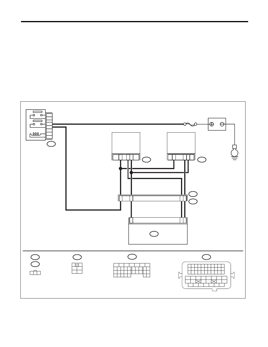
BB:DTC P0345 CAMSHAFT POSITION SENSOR “A” CIRCUIT (BANK 2)
DTC DETECTING CONDITION:
• Immediately at fault recognition
• GENERAL DESCRIPTION <Ref. to GD(H4DOTC)-93, DTC P0345 CAMSHAFT POSITION SENSOR “A”
CIRCUIT (BANK 2), Diagnostic Trouble Code (DTC) Detecting Criteria.>
TROUBLE SYMPTOM:
• Engine stalls.
• Failure of engine to start
CAUTION:
After repair or replacement of faulty parts, perform Clear Memory Mode <Ref. to EN(H4DOTC)(diag)-
52, OPERATION, Clear Memory Mode.>, and Inspection Mode <Ref. to EN(H4DOTC)(diag)-43, PRO-
CEDURE, Inspection Mode.>.
WIRING DIAGRAM:
EN-05677
5
6
7
8
2
1
9
4
3
10
24
22 23
25
11 12 13 14 15
26 27
28
16 17
18 19 20 21
33 34
29
32
30 31
B47
1
2
4
6
3
5
E
3
22
SBF-7
E35
E2
B21
2
E36
1
3
11
2
1
B134
3
4
1
2
5
6
E36
B47
1 2 3
B134
E35
21
B21
1 2 3 4
12 13 14 15
5 6 7 8
16 17 18 19
9 10 11
20 21 22
23 24 25 26 27 28 29 30 31 32 33
35
34
37
36
39
38
41
40
43
42
44
45
47
46
49
48
51
50
53
52
54
5
48
2
13
MAIN RELAY
BATTERY
INTAKE
CAMSHAFT
POSITION
SENSOR LH
INTAKE
CAMSHAFT
POSITION
SENSOR RH
ECM

EN(H4DOTC)(diag)-188
Diagnostic Procedure with Diagnostic Trouble Code (DTC)
ENGINE (DIAGNOSTICS)
Step
Check
Yes
No
1
CHECK POWER SUPPLY OF CAMSHAFT
POSITION SENSOR.
1) Turn the ignition switch to OFF.
2) Disconnect the connector from the cam-
shaft position sensor.
3) Turn the ignition switch to ON.
4) Measure the voltage between camshaft
position sensor connector and engine ground.
Connector & terminal
(E35) No. 1 (+) — Engine ground (–):
Is the voltage 10 V or more?
Go to step 2.
Repair the harness
and connector.
NOTE:
In this case, repair
the following item:
• Open circuit or
short circuit to
ground in harness
between main re-
lay connector and
camshaft position
sensor connector
• Poor contact of
coupling connector
2
CHECK HARNESS BETWEEN ECM AND
CAMSHAFT POSITION SENSOR CONNEC-
TOR.
1) Turn the ignition switch to OFF.
2) Disconnect the connectors from ECM.
3) Measure the resistance between the ECM
and camshaft position sensor connector.
Connector & terminal
(B134) No. 21 — (E35) No. 2:
(B134) No. 22 — (E35) No. 3:
Is the resistance less than 1
:? Go to step 3.
Repair the harness
and connector.
NOTE:
In this case, repair
the following item:
• Open circuit of
the harness be-
tween the ECM
and camshaft posi-
tion sensor
• Poor contact of
coupling connector
3
CHECK HARNESS BETWEEN ECM AND
CAMSHAFT POSITION SENSOR CONNEC-
TOR.
Measure the resistance between camshaft
position sensor connector and engine ground.
Connector & terminal
(E35) No. 2 — Engine ground:
Is the resistance 1 M
: or
more?
Go to step 4.
Repair the short
circuit to ground in
harness between
ECM and camshaft
position sensor.
4
CHECK HARNESS BETWEEN ECM AND
CAMSHAFT POSITION SENSOR CONNEC-
TOR.
Measure the voltage between camshaft posi-
tion sensor connector and engine ground.
Connector & terminal
(E35) No. 2 (+) — Engine ground (–):
Is the voltage 5 V or more?
Repair the short
circuit to power in
harness between
ECM and camshaft
position sensor.
Go to step 5.
5
CHECK CONDITION OF CAMSHAFT POSI-
TION SENSOR.
Is the camshaft position sensor
installation bolt tightened
securely?
Go to step 6.
Tighten the cam-
shaft position sen-
sor installation bolt
securely.
6
CHECK CAMSHAFT POSITION SENSOR.
Check the waveform of the camshaft position
sensor. <Ref. to EN(H4DOTC)(diag)-17,
Engine Control Module (ECM) I/O Signal.>
Is there any abnormality in
waveform?
Replace the cam-
shaft position sen-
sor. <Ref. to
FU(H4DOTC)-33,
Camshaft Position
Sensor.>
Repair the follow-
ing item.
• Poor contact in
ECM connector
• Poor contact of
camshaft position
sensor connector
• Poor contact of
coupling connector
Нет комментариевНе стесняйтесь поделиться с нами вашим ценным мнением.
Текст