Subaru Legacy IV (2008 year). Service manual — part 951
BR-16
Front Disc Brake Assembly
BRAKE
7) Connect the brake hose using a new brake hose
gasket.
Tightening torque:
18 N·m (1.8 kgf-m, 13.0 ft-lb)
8) Bleed air from the brake system.
2. 17-INCH TYPE
1) Apply a thin coat of Molykote M7439 (Part No.
K0777YA000) or grease contained in the pad kit to
the support.
2) Install the support to the housing.
Tightening torque:
120 N·m (12.2 kgf-m, 88.5 ft-lb)
3) Apply a thin coat of Molykote M7439 (Part No.
K0777YA000) or grease contained in the pad kit to
the pad clip.
4) Apply a thin coat of Molykote AS880N (Part No.
K0779YA010) or grease contained in the pad kit to
both surfaces of the pad inner shim.
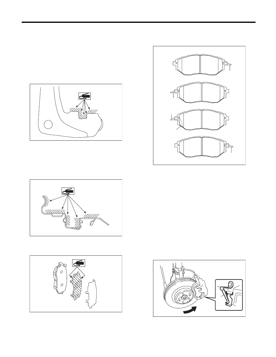
5) Install the pad to support.
NOTE:
Install the pad indicator in proper direction.
CAUTION:
• Be sure to install so that the pad return
spring faces the input side of the direction of
brake rotor rotation, as shown in the figure.
• Correctly install the pad return spring to the
supporting surface of the pad clip as shown in
the figure.
• If the pad return spring is deformed or dam-
aged, replace the brake pad.
BR-00597
BR-00596
BR-00601
(1) LH — IN
(2) LH — OUT
(3) RH — IN
(4) RH — OUT
(5) Pad indicator
(6) Pad return spring
(1) Pad return spring
(2) Supporting surface of pad clip
(3) Direction of brake rotor rotation
BR-00586
(6)
(6)
(6)
(1)
(2)
(3)
(4)
(5)
(6)
BR-00483
(1)
(2)
(3)
BR-17
Front Disc Brake Assembly
BRAKE
6) Install the caliper body to the support.
7) Connect the brake hose using a new brake hose
gasket.
Tightening torque:
18 N·m (1.8 kgf-m, 13.0 ft-lb)
8) Bleed air from the brake system.
C: DISASSEMBLY
1. 16-INCH TYPE
1) Remove mud and foreign matter from the caliper
body assembly and the support.
CAUTION:
Be careful not to allow foreign matter to enter
the brake hose connector.
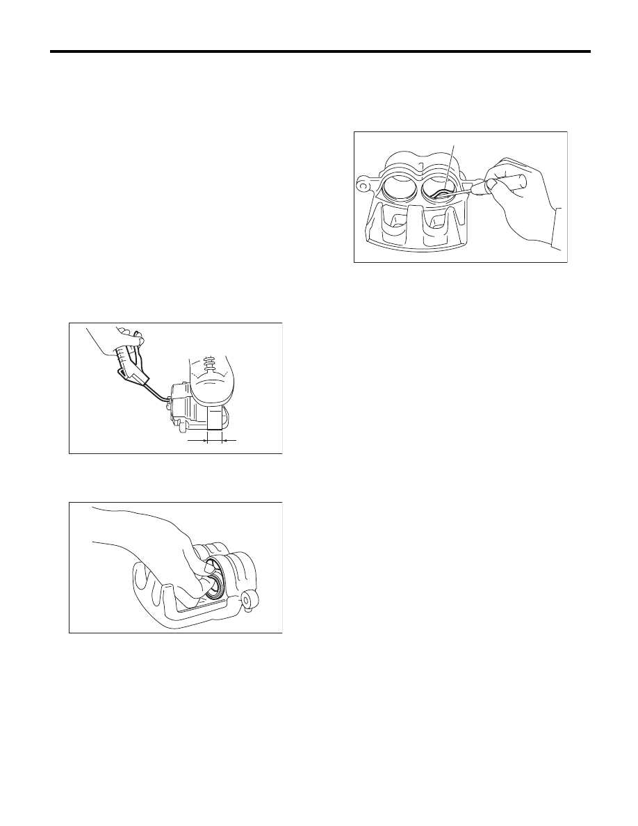
2) Place a wooden block in the caliper body as
shown in the figure to prevent the piston from jump-
ing out and being damaged.
3) Gradually apply compressed air via the brake
hose installation hole to push the piston out.
4) Remove the piston boot.
5) Remove the piston seal from caliper body cylin-
der.
CAUTION:
Do not damage the cylinder and piston seal
groove.
6) Remove the guide pin and boot from caliper
body.
2. 17-INCH TYPE
Refer to 16-inch type. <Ref. to BR-17, 16-INCH
TYPE, DISASSEMBLY, Front Disc Brake Assem-
bly.>
(1) Place a wooden block of 30 mm (1.18 in) width.
(1)
BR-00026
BR-00240
(1) Piston seal
(1)
BR-00027
BR-18
Front Disc Brake Assembly
BRAKE
D: ASSEMBLY
1. 16-INCH TYPE
1) Clean the inside of the caliper body using brake
fluid.
2) Apply a coat of brake fluid to piston seal and in-
stall the piston seal to the caliper body groove.
3) Apply a coat of brake fluid to the inner surface of
cylinder and the entire outer surface of the piston.
4) Apply grease contained in the piston seal kit to
the boot, and install it to the groove at the end of the
cylinder.
5) Insert the piston into cylinder.
CAUTION:
Do not force the piston into cylinder.
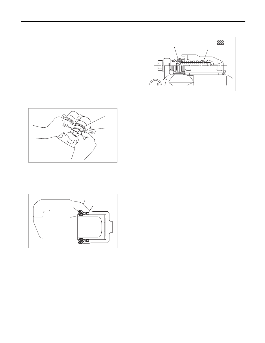
6) Position the boot in the grooves on cylinder and
piston.
7) Apply grease contained in the piston seal kit to
the lock pin, guide pin outer surface, cylinder inner
surface, and boot grooves.
8) Insert the lock pin and guide pin boot into the
support.
CAUTION:
After inserting the lock pin and guide pin into
the specified locations, check by hand that the
pin moves and slides smoothly with no abnor-
malities when it reaches the end.
2. 17-INCH TYPE
Refer to 16-inch type. <Ref. to BR-18, 16-INCH
TYPE, ASSEMBLY, Front Disc Brake Assembly.>
E: INSPECTION
1) Repair or replace the faulty parts.
2) Check the caliper body and piston for uneven
wear, damage or rust.
3) Check the rubber parts for damage or deteriora-
tion.
(1) Piston
(2) Piston boot
(1) Piston
(2) Piston boot
(3) Caliper body
(4) Piston seal
BR-00242
(1)
(2)
BR-00243
(1)
(2)
(3)
(4)
(1) Pin boot
(2) Lock pin or guide pin
(3) Grease applied area
BR-00362
(1)
(2)
: (3)
BR-19
Rear Brake Pad
BRAKE
5. Rear Brake Pad
A: REMOVAL
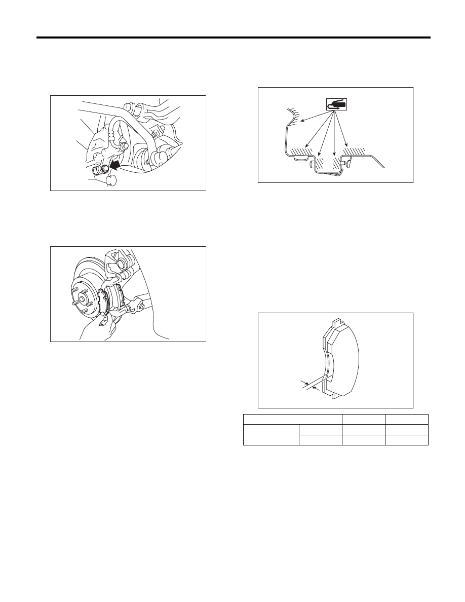
1) Lift up the vehicle, and remove the rear wheels.
2) Remove the caliper bolt.
3) Raise the caliper body and support it.
NOTE:
Do not disconnect the brake hose from the caliper
body.
4) Remove the pads.
B: INSTALLATION
1) Apply a thin coat of Molykote M7439 (Part No.
K0777YA000) or grease contained in the pad kit to
the pad clip.
2) Apply a thin coat of Molykote AS880N (Part No.
K0779YA010) or grease contained in the pad kit to
the contact surface between the pad and shim.
3) Install the pad to support.
4) Install the caliper body to the support.
Tightening torque:
Solid disc brake model
27 N·m (2.8 kgf-m, 19.9 ft-lb)
Ventilated disc brake model
37 N·m (3.7 kgf-m, 27.2 ft-lb)
C: INSPECTION
Check the pad thickness A.
NOTE:
• Always replace the pads of both wheels and both
sides as a set.
• Replace pad clips if they are twisted or worn.
• A wear indicator is installed on the inner disc
brake pad. If the pad is worn to the limit, the end of
wear indicator contacts disc rotor, and a squeaking
sound is heard as the wheel rotates. If the sound is
heard, replace the pad.
• Replace the pad if there is oil or grease on it.
BR-00344
BR-00032
Type of disc rotor
Solid
Ventilated
Pad thickness
Standard
9.0 (0.35)
9.0 (0.35)
mm (in) Wear limit
1.5 (0.059)
1.5 (0.059)
BR-00599
A
BR-00016
Нет комментариевНе стесняйтесь поделиться с нами вашим ценным мнением.
Текст