Subaru Legacy IV (2008 year). Service manual — part 950
BR-12
Front Brake Pad
BRAKE
2. Front Brake Pad
A: REMOVAL
1. 16-INCH TYPE
1) Lift up the vehicle, and remove the front wheels.
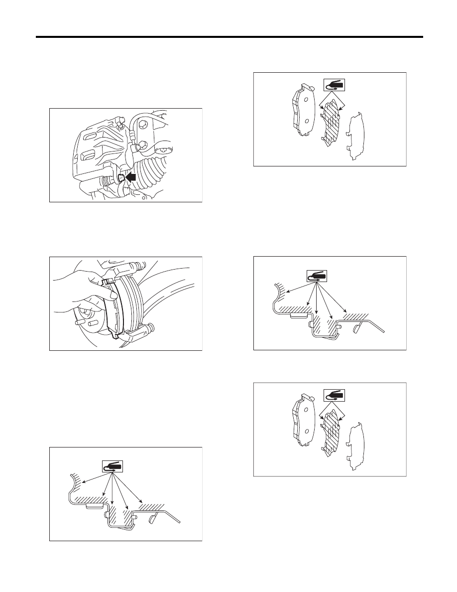
2) Remove the caliper bolt.
3) Raise the caliper body and support it.
NOTE:
Do not disconnect the brake hose from the caliper
body.
4) Remove the pad.
2. 17-INCH TYPE
Refer to 16-inch type. <Ref. to BR-12, 16-INCH
TYPE, REMOVAL, Front Brake Pad.>
B: INSTALLATION
1. 16-INCH TYPE
1) Apply a thin coat of Molykote M7439 (Part No.
K0777YA000) or grease contained in the pad kit to
the pad clip.
2) Apply a thin coat of Molykote AS880N (Part No.
K0779YA010) or grease contained in the pad kit to
both surfaces of the pad inner shim.
3) Install the pad to support.
4) Install the caliper body to the support.
Tightening torque:
27 N·m (2.8 kgf-m, 19.9 ft-lb)
2. 17-INCH TYPE
1) Apply a thin coat of Molykote M7439 (Part No.
K0777YA000) or grease contained in the pad kit to
the pad clip.
2) Apply a thin coat of Molykote AS880N (Part No.
K0779YA010) or grease contained in the pad kit to
both surfaces of the pad inner shim.
BR-00339
BR-00012
BR-00596
BR-00601
BR-00596
BR-00601
BR-13
Front Brake Pad
BRAKE
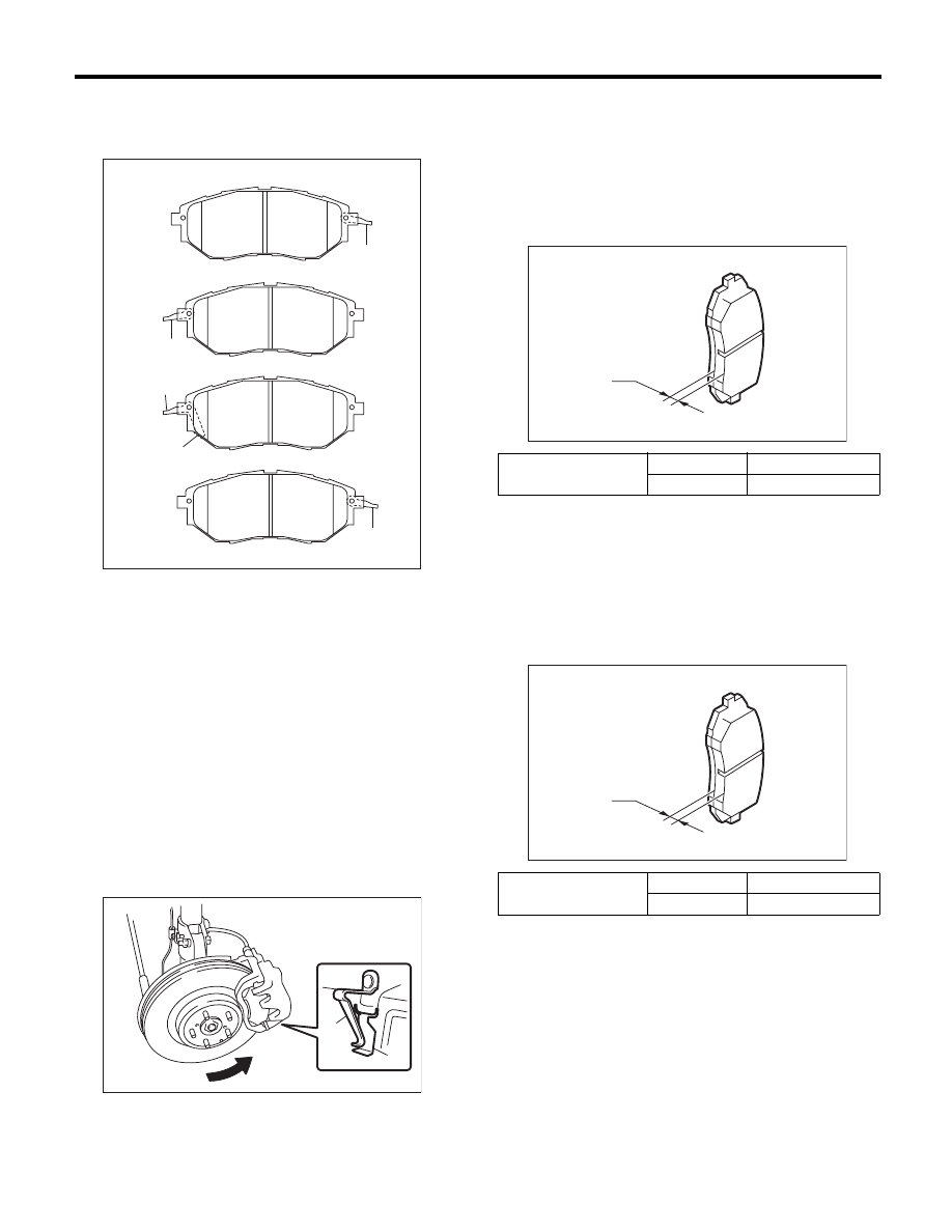
3) Install the pad to support.
NOTE:
Install the pad indicator in proper direction.
CAUTION:
• Be sure to install so that the pad return
spring faces the input side of the direction of
brake rotor rotation, as shown in the figure.
• Correctly install the pad return spring to the
supporting surface of the pad clip as shown in
the figure.
• If the pad return spring is deformed or dam-
aged, replace the brake pad.
4) Install the caliper body to the support.
Tightening torque:
27 N·m (2.8 kgf-m, 19.9 ft-lb)
C: INSPECTION
1. 16-INCH TYPE
Check thickness A of the pad.
NOTE:
• Always replace the pads of both wheels and both
sides as a set.
• Replace pad clips if they are twisted or worn.
• Replace the pad if there is oil or grease on it.
2. 17-INCH TYPE
Check the pad thickness A.
NOTE:
• Always replace the pads of both wheels and both
sides as a set.
• Replace the pad if there is oil or grease on it.
(1) LH — IN
(2) LH — OUT
(3) RH — IN
(4) RH — OUT
(5) Pad indicator
(6) Pad return spring
(1) Pad return spring
(2) Supporting surface of pad clip
(3) Direction of brake rotor rotation
BR-00586
(6)
(6)
(6)
(1)
(2)
(3)
(4)
(5)
(6)
BR-00483
(1)
(2)
(3)
Pad thickness mm (in)
Standard
11 (0.43)
Wear limit
1.5 (0.059)
Pad thickness mm (in)
Standard
11 (0.43)
Wear limit
1.5 (0.059)
BR-00360
A
BR-00360
A
BR-14
Front Disc Rotor
BRAKE
3. Front Disc Rotor
A: REMOVAL
1. 16-INCH TYPE
1) Lift up the vehicle, and remove the front wheels.
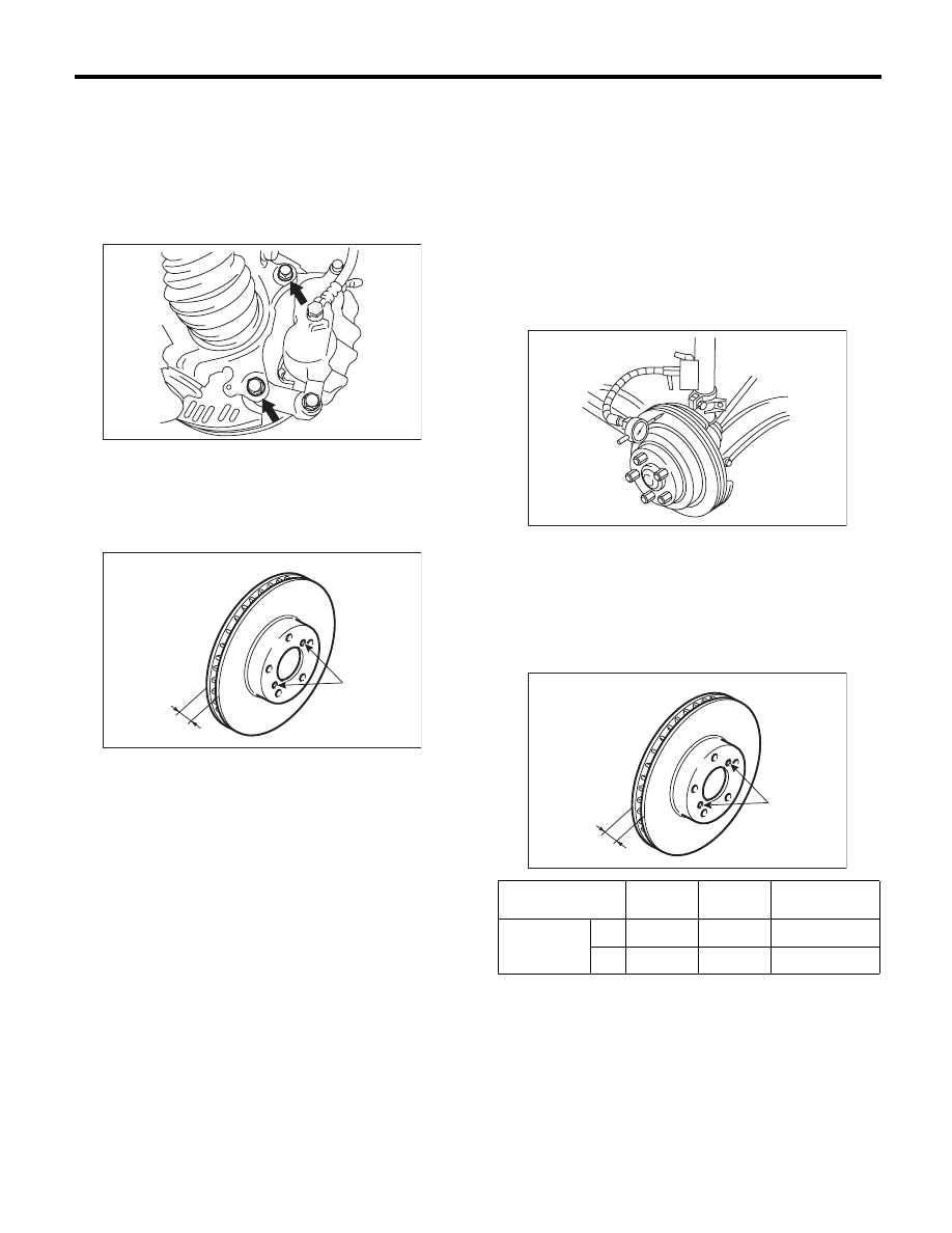
2) Remove the caliper body and the support from
housing, and suspend it from the strut using a wire.
3) Remove the disc rotor.
NOTE:
If it is difficult to remove the disc rotor from the hub,
drive an 8 mm bolt into the threaded section (B) of
the rotor, then remove the rotor.
4) Remove mud and foreign matter from the caliper
body assembly and the support.
2. 17-INCH TYPE
Refer to 16-inch type. <Ref. to BR-14, 16-INCH
TYPE, REMOVAL, Front Disc Rotor.>
B: INSTALLATION
1) Install the disc rotor.
2) Install the caliper body and the support to hous-
ing.
Tightening torque:
120 N·m (12.2 kgf-m, 88.5 ft-lb)
3) Install the front wheels.
C: INSPECTION
1) Check the front wheel bearing play and axle hub
runout before the inspection of disc rotor runout
limit. <Ref. to DS-16, INSPECTION, Front Axle.>
2) Secure the disc rotor by tightening the five wheel
nuts.
3) Set a dial gauge 10 mm (0.39 in) inward from the
disc rotor outer circumference. Rotate the disc rotor
to check runout. If the disc rotor runout exceeds the
limit, resurface the disc rotor. After grinding, check
the thickness of the disc rotor according to the pro-
cedure in step 4).
Disc rotor runout limit:
0.05 mm (0.0020 in)
4) Set a micrometer 10 mm (0.39 in) inward from
the disc rotor outer perimeter, and then measure
the disc rotor thickness. If the thickness of disc ro-
tor exceeds the service limit, replace with a new
disc rotor.
BR-00017
B
A
BR-00018
Standard
Limit
Disc rotor outer
diameter
Disc rotor
thickness A
mm (in)
16
s
24 (0.94)
22 (0.87)
294 (11.57)
17
s
30 (1.18)
28 (1.10)
316 (12.44)
BR-00019
B
A
BR-00018
BR-15
Front Disc Brake Assembly
BRAKE
4. Front Disc Brake Assembly
A: REMOVAL
1. 16-INCH TYPE
CAUTION:
Do not allow brake fluid to come in contact with
vehicle body. If it does, wash off with water and
wipe away completely.
1) Lift up the vehicle, and remove the front wheels.
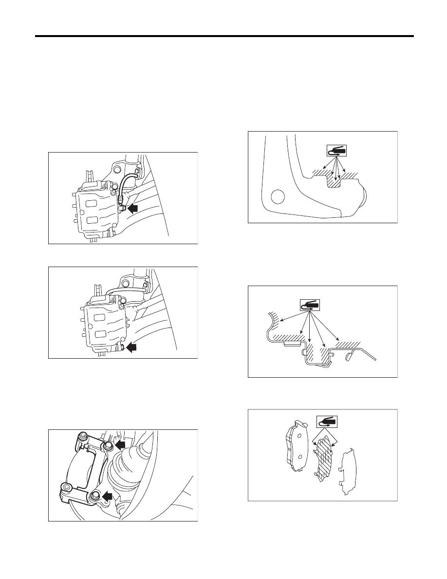
2) Remove the union bolt, and disconnect the
brake hose from the caliper body assembly.
3) Remove the bolt securing the lock pin to caliper
body.
4) Raise the caliper body, and then move it toward
vehicle center to separate it from the support.
5) Remove the support from housing.
NOTE:
Remove the support only when replacing the rotor
or support. It is not necessary to remove it when
servicing the caliper body assembly.
6) Remove mud and foreign matter from the caliper
body assembly and the support.
2. 17-INCH TYPE
Refer to 16-inch type. <Ref. to BR-15, 16-INCH
TYPE, REMOVAL, Front Disc Brake Assembly.>
B: INSTALLATION
1. 16-INCH TYPE
1) Apply a thin coat of Molykote M7439 (Part No.
K0777YA000) or grease contained in the pad kit to
the support.
2) Install the support to the housing.
Tightening torque:
120 N·m (12.2 kgf-m, 88.5 ft-lb)
3) Apply a thin coat of Molykote M7439 (Part No.
K0777YA000) or grease contained in the pad kit to
the pad clip.
4) Apply a thin coat of Molykote AS880N (Part No.
K0779YA010) or grease contained in the pad kit to
both surfaces of the pad inner shim.
5) Install the pad to support.
6) Install the caliper body to the support.
Tightening torque:
27 N·m (2.8 kgf-m, 19.9 ft-lb)
BR-00021
BR-00022
BR-00023
BR-00597
BR-00596
BR-00601
Нет комментариевНе стесняйтесь поделиться с нами вашим ценным мнением.
Текст