Subaru Legacy IV (2008 year). Service manual — part 813
6MT-65
Main Shaft Assembly
MANUAL TRANSMISSION AND DIFFERENTIAL
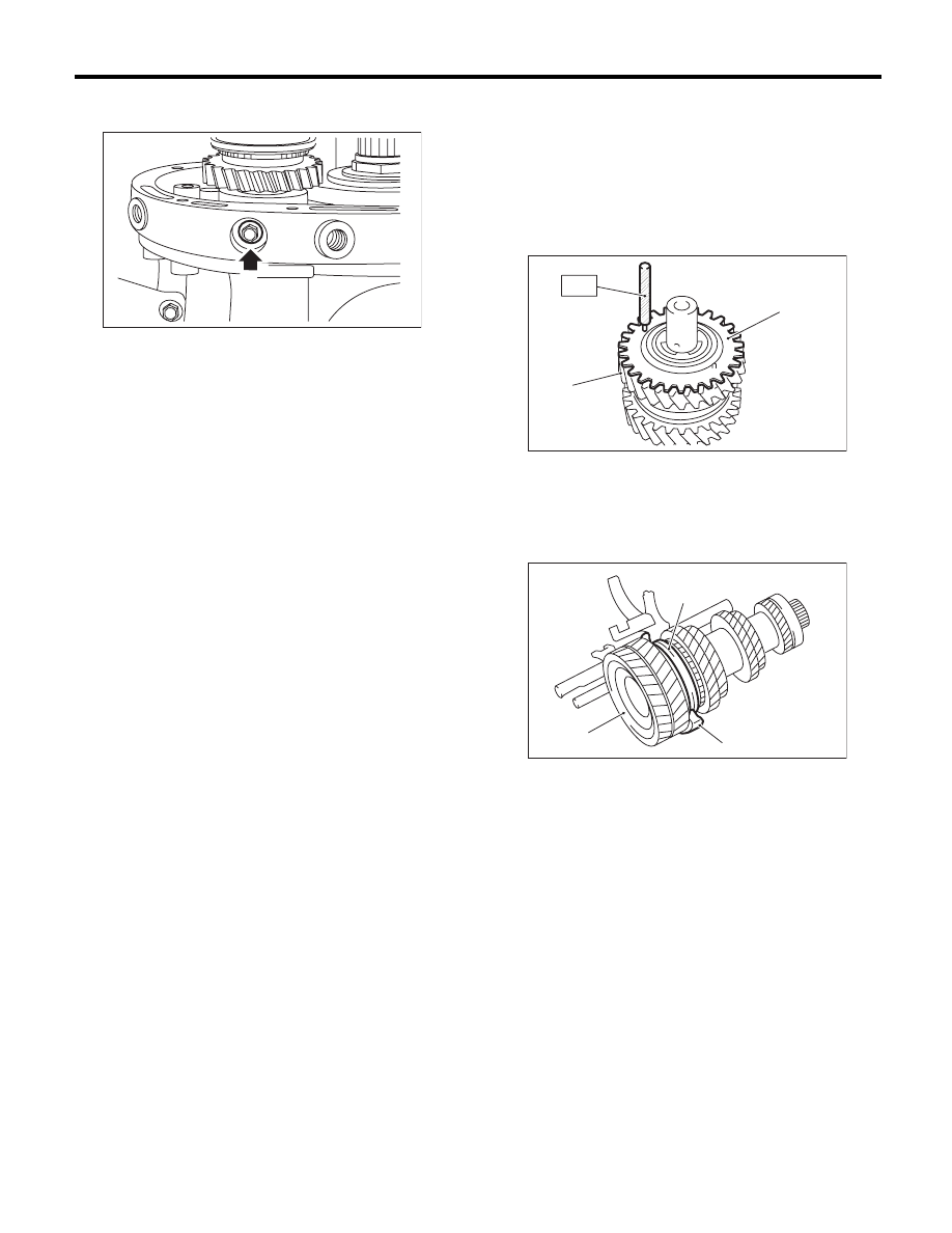
13) Remove the bolt and gasket holding the re-
verse idler shaft.
14) Push the main shaft assembly, driven gear as-
sembly, reverse idler gear and shifter forks to re-
move from the adapter plate all at once.
NOTE:
A helper is required to perform this work.
B: INSTALLATION
1) Adjust the 3rd-4th and 5th-6th shifter fork rods.
<Ref. to 6MT-115, ADJUSTMENT, Shifter Fork
and Rod.>
2) Turn the sub gear counterclockwise for approxi-
mately 3 teeth. Match the sub gear and reverse
idler gear holes, and insert the ST.
ST
18757AA000
STRAIGHT PIN
3) Attach the driven gear assembly to the 1st-2nd
shifter fork assembly.
MT-00546
(A) Sub gear
(B) Reverse idler gear
(A) 1st-2nd shifter fork
(B) Driven gear ASSY
(C) 1st-2nd sleeve
MT-00547
(A)
(B)
ST
MT-00548
(A)
(B)
(C)
6MT-66
Main Shaft Assembly
MANUAL TRANSMISSION AND DIFFERENTIAL
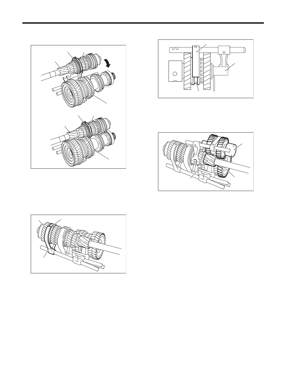
4) Attach the main shaft assembly to the 3rd-4th
shifter fork, and assemble to the driven gear as-
sembly.
5) Attach the 5th-6th shifter fork assembly to the
main shaft assembly.
6) Attach the reverse shifter fork assembly to the
reverse idler gear assembly.
7) Install the reverse idler gear assembly.
8) Install the thrust bearing of the driven gear as-
sembly.
9) Push on the shifter forks, main shaft assembly,
driven gear assembly and reverse idler gear as-
semblies, to attach to the adapter plate all at once.
NOTE:
A helper is required to perform this work.
(A) 3rd-4th shifter fork
(B) 3rd-4th sleeve
(C) Driven gear ASSY
(D) Main shaft ASSY
(A) 5th-6th shifter fork
(B) 5th-6th sleeve
(C) Main shaft ASSY
MT-00549
(C)
(A)
(B)
(C)
(D)
(D)
(A)
(B)
MT-00550
(B)
(A)
(C)
(A) Reverse idler gear ASSY
(B) Reverse shifter fork
(C) Reverse sleeve
(A) Reverse idler gear ASSY
(B) 1st drive gear
(C) Reverse gear
MT-00551
(A)
(B)
(C)
MT-00552
(B)
(A)
(C)
6MT-67
Main Shaft Assembly
MANUAL TRANSMISSION AND DIFFERENTIAL
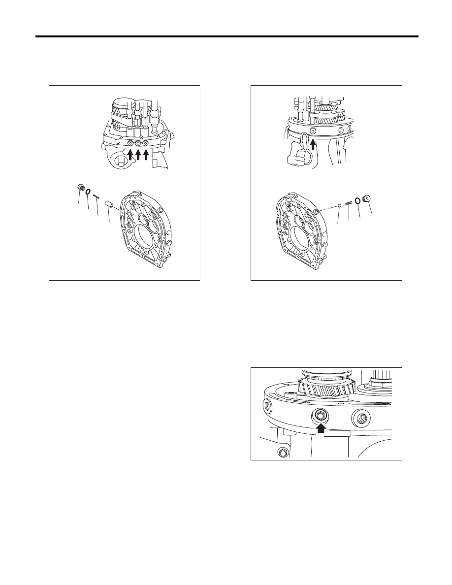
10) Install the plunger, check spring, new O-ring
and check plugs.
Tightening torque:
25 N·m (2.5 kgf-m, 18.4 ft-lb)
11) Install the check ball, check spring, new O-ring
and check plugs.
Tightening torque:
25 N·m (2.5 kgf-m, 18.4 ft-lb)
12) Install a bolt and a new gasket.
Tightening torque:
25 N·m (2.5 kgf-m, 18.4 ft-lb)
13) Use a screwdriver to shift to the 4th gear posi-
tion.
(A) Check plug
(B) O-ring
(C) Check spring
(D) Plunger
MT-00553
(D)
(A)
(B)
(C)
(A) Check plug
(B) O-ring
(C) Check spring
(D) Check ball
MT-00554
(D)
(A)
(B)
(C)
MT-00546
6MT-68
Main Shaft Assembly
MANUAL TRANSMISSION AND DIFFERENTIAL
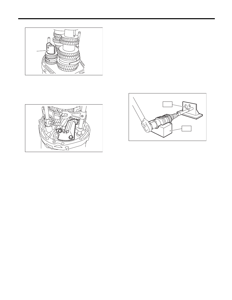
14) Install the reverse idler holder.
15) Install the oil guide B.
Tightening torque:
18 N·m (1.8 kgf-m, 13.3 ft-lb)
16) Install the striking rod.
17) Install the transmission case. <Ref. to 6MT-60,
INSTALLATION, Transmission Case.>
18) Install the selected main shaft snap ring and
washers.
19) Install the center differential. <Ref. to 6MT-57,
INSTALLATION, Center Differential.>
20) Install the transfer driven gear. <Ref. to 6MT-
55, INSTALLATION, Transfer Driven Gear.>
21) Install the extension case. <Ref. to 6MT-43, IN-
STALLATION, Extension Case.>
22) Install the neutral position switch, back-up light
switch and harness. <Ref. to 6MT-41, INSTALLA-
TION, Neutral Position Switch.> <Ref. to 6MT-39,
INSTALLATION, Back-up Light Switch.>
23) Install the manual transmission assembly to the
vehicle. <Ref. to 6MT-34, INSTALLATION, Manual
Transmission Assembly.>
C: DISASSEMBLY
NOTE:
Individual sleeves and hubs meet at a specified po-
sition. Before disassembly, mark the meeting posi-
tion of the sleeve and hub.
1) Affix the ST to the work table.
ST
18664AA000
BASE
2) Flatten the tab of the lock nut.
3) Set the main shaft assembly to the ST, and re-
move the lock nut and washer.
ST1
18665AA000
HOLDER
ST2
18664AA000
BASE
NOTE:
Use a 38 mm socket wrench.
4) Remove the main shaft assembly from the ST.
(A) Reverse idler holder
MT-00544
(A)
MT-01623
MT-00556
ST2
ST1
Нет комментариевНе стесняйтесь поделиться с нами вашим ценным мнением.
Текст