Subaru Legacy IV (2008 year). Service manual — part 811
6MT-57
Center Differential
MANUAL TRANSMISSION AND DIFFERENTIAL
15.Center Differential
A: REMOVAL
1) Remove the manual transmission case from the
vehicle. <Ref. to 6MT-32, REMOVAL, Manual
Transmission Assembly.>
2) Prepare the transmission for overhaul. <Ref. to
6MT-37, Preparation for Overhaul.>
3) Remove the extension case. <Ref. to 6MT-43,
REMOVAL, Extension Case.>
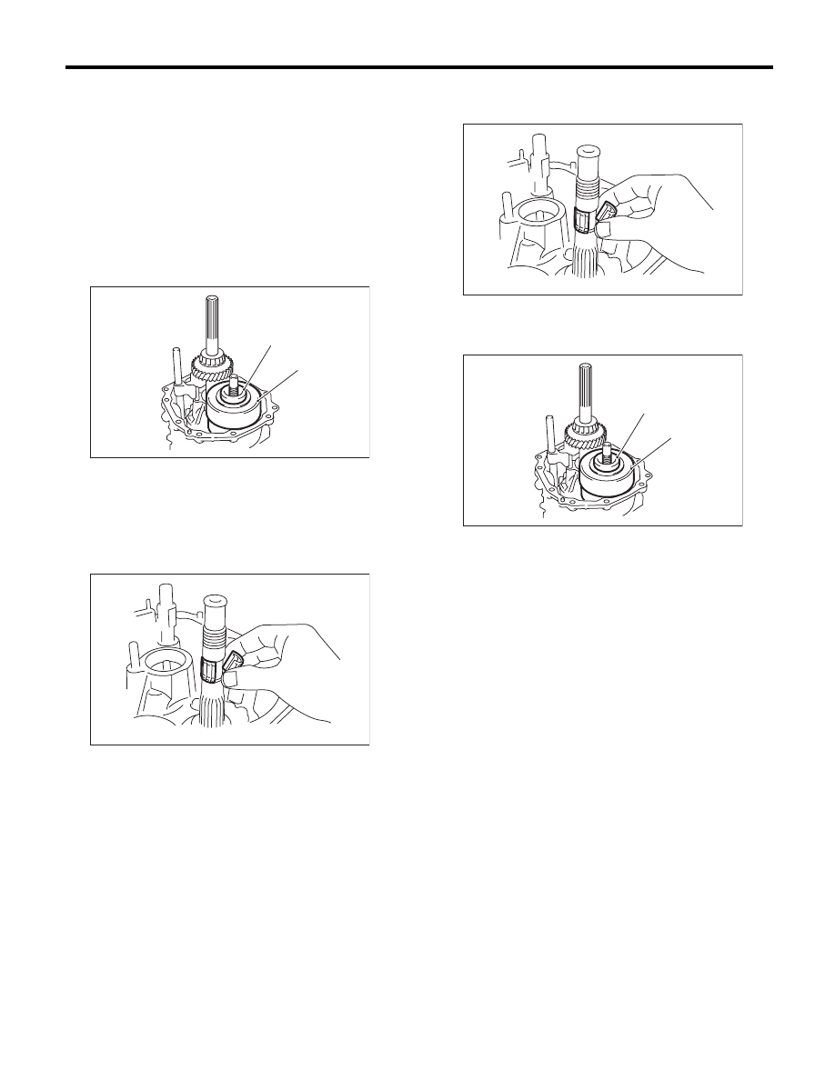
4) Remove the thrust washer and center differen-
tial.
5) Remove the transfer driven gear. <Ref. to 6MT-
55, REMOVAL, Transfer Driven Gear.>
6) Remove the needle bearing.
B: INSTALLATION
1) Install the needle bearing.
2) Install the transfer driven gear. <Ref. to 6MT-55,
INSTALLATION, Transfer Driven Gear.>
3) Install the thrust washer and center differential.
4) When replacing the center differential, select
and install the appropriate transfer drive gear and
thrust washer. <Ref. to 6MT-46, ADJUSTMENT,
Extension Case.>
5) Install the extension case. <Ref. to 6MT-43, IN-
STALLATION, Extension Case.>
6) Install the manual transmission case assembly
to the vehicle. <Ref. to 6MT-34, INSTALLATION,
Manual Transmission Assembly.>
C: INSPECTION
Check that there is no damage on the center differ-
ential. Replace if damaged.
(A) Thrust washer
(B) Center differential
MT-00515
(A)
(B)
MT-00516
(A) Thrust washer
(B) Center differential
MT-00516
MT-00515
(A)
(B)
6MT-58
Transmission Case
MANUAL TRANSMISSION AND DIFFERENTIAL
16.Transmission Case
A: REMOVAL
1) Remove the manual transmission assembly
from the vehicle. <Ref. to 6MT-32, REMOVAL,
Manual Transmission Assembly.>
2) Prepare the transmission for overhaul. <Ref. to
6MT-37, Preparation for Overhaul.>
3) Remove the neutral position switch, back-up
light switch and harness. <Ref. to 6MT-41, RE-
MOVAL, Neutral Position Switch.> <Ref. to 6MT-
39, REMOVAL, Back-up Light Switch.>
4) Remove the extension case. <Ref. to 6MT-43,
REMOVAL, Extension Case.>
5) Remove the transfer driven gear. <Ref. to 6MT-
55, REMOVAL, Transfer Driven Gear.>
6) Remove the center differential. <Ref. to 6MT-57,
REMOVAL, Center Differential.>
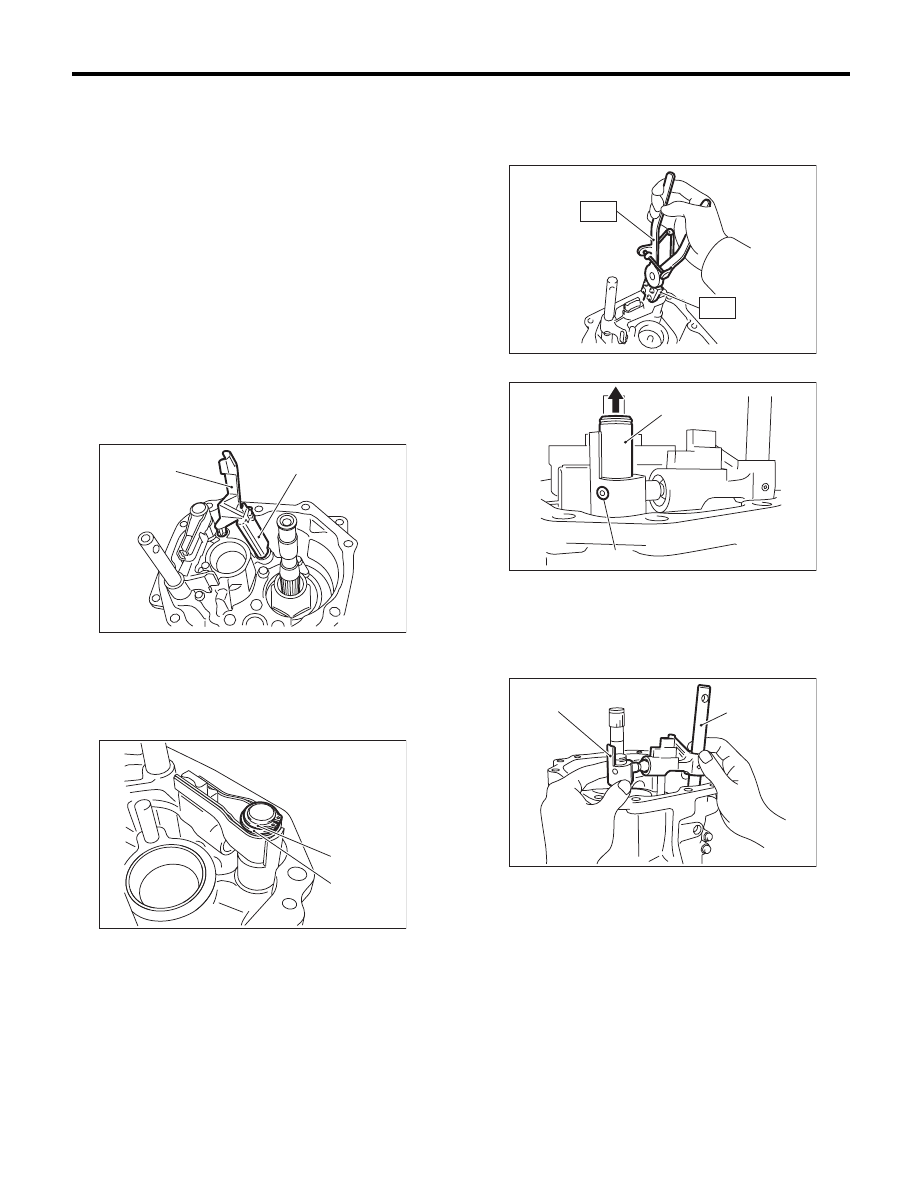
7) Remove the oil guides G and H.
8) Remove the snap ring and flat washer from the
selector arm area.
9) Using an ST, remove the neutral set spring and
support.
ST1
18756AA000
CLAW
ST2
399893600
PLIER
10) Lift the striking rod, and remove the spring pin.
11) Remove the selector arm No. 2 and the shifter
arm.
(A) Oil guide G
(B) Oil guide H
(A) Snap ring
(B) Flat washer
MT-01728
(A)
(B)
MT-01616
(B)
(A)
(A) Striking rod
(B) Spring pin
(A) Selector arm No. 2
(B) Shifter arm
MT-01092
ST2
ST1
MT-01307
(A)
(B)
(B)
(A)
MT-01618
6MT-59
Transmission Case
MANUAL TRANSMISSION AND DIFFERENTIAL
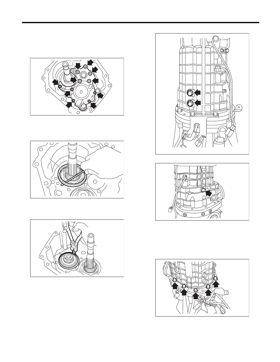
12) Remove the transfer bearing holder.
NOTE:
Using a general tool may cause damage. Remove
the bolt using the ST.
ST
18663AA000
SOCKET
13) Remove the thrust washer on the main shaft
section.
14) Remove the driven gear assembly shim and
spacer.
15) Remove the snap ring.
16) Remove the pilot bolt.
17) Remove the holder reverse bolt.
18) Remove the transmission case.
NOTE:
If the oil guide is caught between the shift fork, it
may be difficult to remove the transmission case.
Move the oil guide, then remove. Do not pull on the
transmission case with excessive force.
19) Remove any remaining liquid gasket from the
transmission case and adapter plate.
(A) Driven gear ASSY
MT-01619
(A)
MT-00526
MT-00527
MT-00528
MT-00529
MT-00530
6MT-60
Transmission Case
MANUAL TRANSMISSION AND DIFFERENTIAL
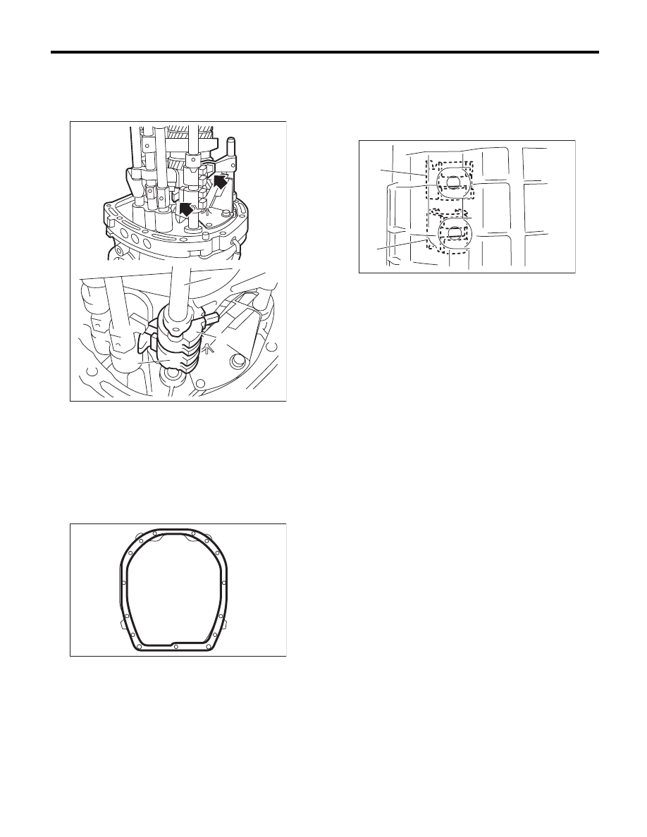
B: INSTALLATION
1) Check that the shifter fork and the interlock block
are both shifted into the neutral position. If they are
not, shift into the neutral position.
2) Apply liquid gasket to the adapter plate.
Liquid gasket:
THREE BOND 1215 (Part No. 004403007) or
equivalent
3) Install the transmission case.
4) By inspecting from the pilot bolt attachment hole,
check that the interlock block and the reverse inter-
lock block are aligned to the neutral position. If not
aligned, remove the transmission case, and shift
the shifter fork and interlock block to the neutral po-
sition.
5) Use a new gasket to temporarily attach the pilot
bolt.
6) Affix the transmission case with the bolts and
nuts.
Tightening torque:
50 N·m (5.1 kgf-m, 36.9 ft-lb)
7) Tighten the pilot bolt.
Tightening torque:
34 N·m (3.5 kgf-m, 25.1 ft-lb)
8) Tighten the holder reverse bolt.
Tightening torque:
25 N·m (2.5 kgf-m, 18.4 ft-lb)
(A) Striking rod
(B) Reverse interlock block
(C) Interlock block
(A)
(C)
(B)
MT-01620
MT-00532
(A) Interlock block
(B) Reverse interlock block
MT-00533
(A)
(B)
Нет комментариевНе стесняйтесь поделиться с нами вашим ценным мнением.
Текст