Subaru Legacy IV (2008 year). Service manual — part 651
CS-11
AT Shift Lock Control System
CONTROL SYSTEMS
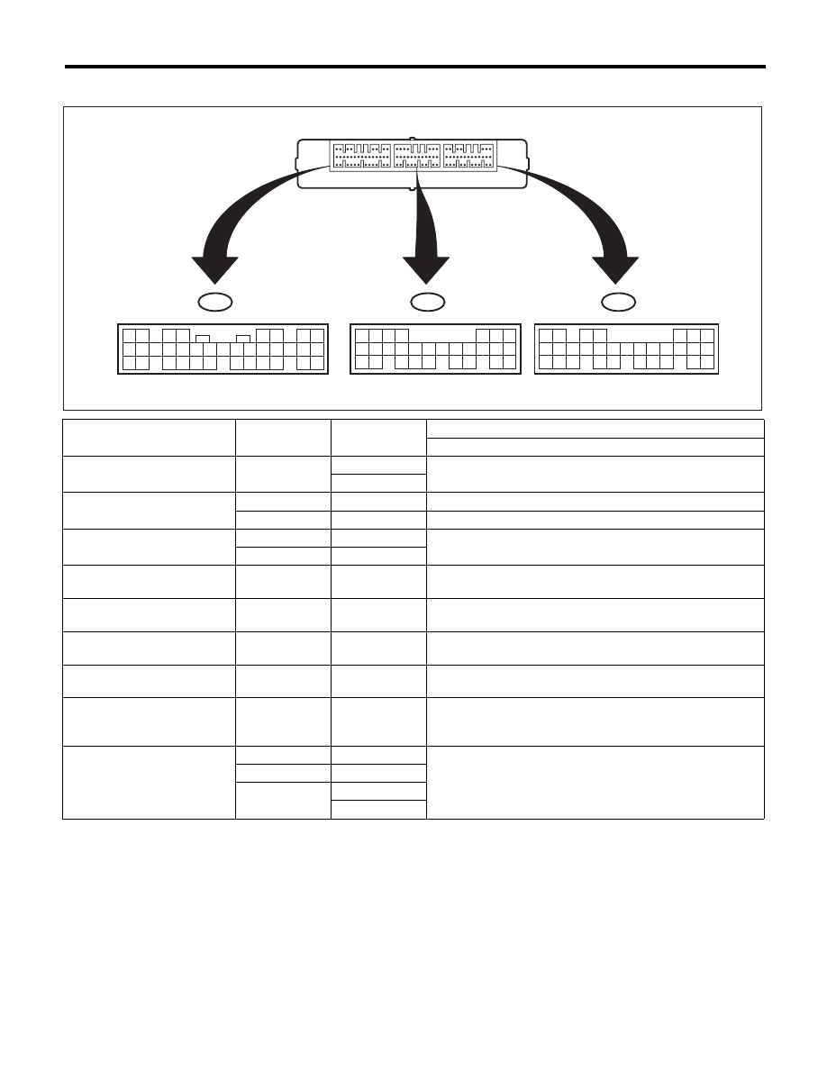
B: ELECTRICAL SPECIFICATION
Item
Connector No.
Terminal No.
Input/Output signal
Measured value and measuring conditions
Battery power supply
B281
1
9 — 16 V
2
Ignition power supply
i84
1
10 — 15 V when ignition switch is at ON or START.
i84
24
10 — 15 V when ignition switch is at ACC.
TCM (“P” range)
B280
20
Pulse signal
B280
30
Stop light switch
B281
23
9 — 16 V when stop light switch is ON.
0 V when stop light switch is OFF.
“P” range switch
B281
13
0 V when select lever is in “P” range.
9 — 16 V when select lever is in other ranges than “P” range.
Shift lock solenoid signal
B280
6
8.5 — 16 V when shift lock is released.
0 V when shift lock is operating.
Key warning switch signal
B281
7
9 — 16 V when key is inserted.
0 V when key is removed.
Key lock solenoid signal
B280
5
7.5 — 16 V when ignition switch is turned ON, with select
lever in “P” range and brake switch ON.
0 V at other conditions than above.
Ground
B280
22
—
i84
21
B281
8
9
SL-00692
7
19
28
6
18
27
5
17
4
16
26
15
25
14
24
13 12
23
11
22
3
10
2
9
21
1
8
20
7
20
30
6
19
29
18
28
5
17
4
16
27
15
26
14 13
25
12
24
11
23
3
10
2
9
22
1
8
21
B280
B281
8
23
35
7
22
34
21
6
20
33
5
19
32
18
31
17
30
16 15
29
14
28
4
13
27
3
12
26
11
2
10
25
1
9
24
i84
A:
B:
C:
TO
TO
TO
CS-12
AT Shift Lock Control System
CONTROL SYSTEMS
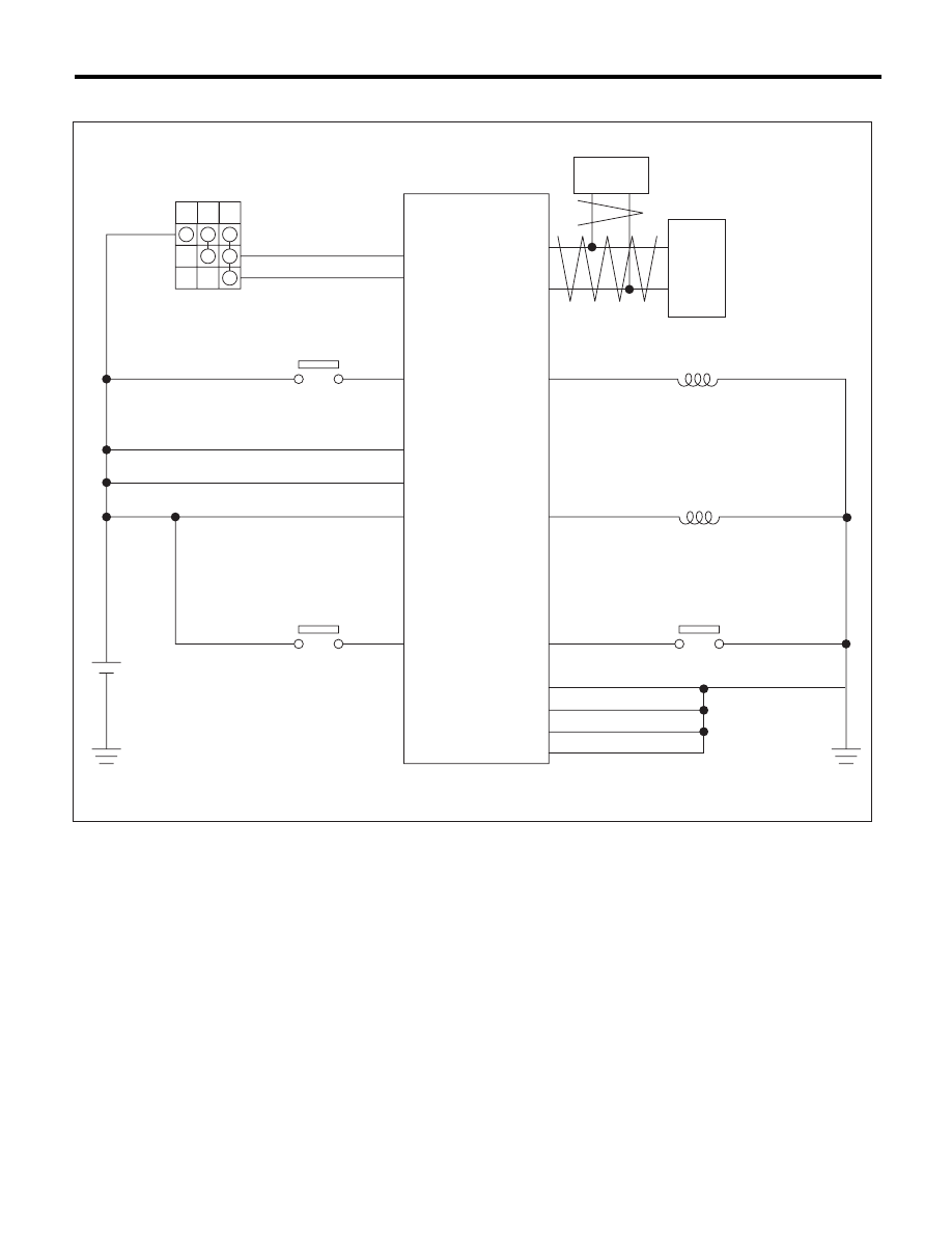
C: WIRING DIAGRAM
(1)
Ignition switch
(5)
TCM (shift range information)
(8)
“P” range switch
(2)
Stop light switch
(6)
Key lock solenoid
(9)
Battery
(3)
Key warning switch
(7)
Shift lock solenoid
(10)
VDC/ABS (vehicle speed signal)
(4)
Body integrated unit
OFF ACC ON
(1)
(2)
(3)
(4)
(9)
(6)
(7)
(8)
(5)
(10)
CS-00909

CS-13
AT Shift Lock Control System
CONTROL SYSTEMS
D: INSPECTION
1. SHIFT LOCK OPERATION
Step
Check
Yes
No
1
CHECK COMMUNICATION OF SUBARU SE-
LECT MONITOR.
1) Turn the ignition switch to ON.
2) Using the Subaru Select Monitor, check
whether communication to all systems can be
executed normally.
Is the system name displayed? Go to step 2.
Perform the
inspection follow-
ing the diagnostic
procedure in the
LAN section. <Ref.
to LAN(diag)-2,
Basic Diagnostic
Procedure.>
2
CHECK SHIFT LOCK.
1) Turn the ignition switch to ON.
2) Shift the select lever to the “P” range.
While brake pedal is not
depressed, is it possible to
move the select lever from the
“P” range to other ranges?
Perform the
inspection of
“SELECT LEVER
CANNOT BE
LOCKED OR
RELEASED”.
<Ref. to CS-17,
SELECT LEVER
CANNOT BE
LOCKED OR
RELEASED,
INSPECTION, AT
Shift Lock Control
System.>
Go to step 3.
3
CHECK SHIFT LOCK.
While brake pedal is
depressed, is it possible to
move the select lever from the
“P” range to other ranges?
Go to step 4.
Perform the
inspection of
“SELECT LEVER
CANNOT BE
LOCKED OR
RELEASED”.
<Ref. to CS-17,
SELECT LEVER
CANNOT BE
LOCKED OR
RELEASED,
INSPECTION, AT
Shift Lock Control
System.>
4
CHECK SHIFT LOCK.
Shift the select lever to “N” range.
Is it possible to move the select
lever from the “N” range to the
“P” range?
Go to step 5.
Perform the
inspection of
“SELECT LEVER
CANNOT BE
LOCKED OR
RELEASED”.
<Ref. to CS-17,
SELECT LEVER
CANNOT BE
LOCKED OR
RELEASED,
INSPECTION, AT
Shift Lock Control
System.>

CS-14
AT Shift Lock Control System
CONTROL SYSTEMS
5
CHECK SHIFT LOCK.
1) Shift the select lever to “N” range.
2) Turn the ignition switch to OFF.
While brake pedal is
depressed, is it possible to
move the select lever from the
“N” range to the “P” range?
Go to step 6.
Perform the
inspection of
“SELECT LEVER
CANNOT BE
LOCKED OR
RELEASED”.
<Ref. to CS-17,
SELECT LEVER
CANNOT BE
LOCKED OR
RELEASED,
INSPECTION, AT
Shift Lock Control
System.>
6
CHECK KEY INTERLOCK.
1) Turn the ignition switch to OFF.
2) Shift the select lever to other than “P” range.
Can the ignition key be
removed?
Perform the
inspection of “KEY
INTERLOCK CAN-
NOT BE LOCKED
OR RELEASED”.
<Ref. to CS-20,
KEY INTERLOCK
CANNOT BE
LOCKED OR
RELEASED,
INSPECTION, AT
Shift Lock Control
System.>
Go to step 7.
7
CHECK KEY INTERLOCK.
Shift the select lever to the “P” range.
Can the ignition key be
removed?
AT shift lock sys-
tem is normal.
Perform the
inspection of “KEY
INTERLOCK CAN-
NOT BE LOCKED
OR RELEASED”.
<Ref. to CS-20,
KEY INTERLOCK
CANNOT BE
LOCKED OR
RELEASED,
INSPECTION, AT
Shift Lock Control
System.>
Step
Check
Yes
No
Нет комментариевНе стесняйтесь поделиться с нами вашим ценным мнением.
Текст