Subaru Legacy IV (2008 year). Service manual — part 652
CS-15
AT Shift Lock Control System
CONTROL SYSTEMS
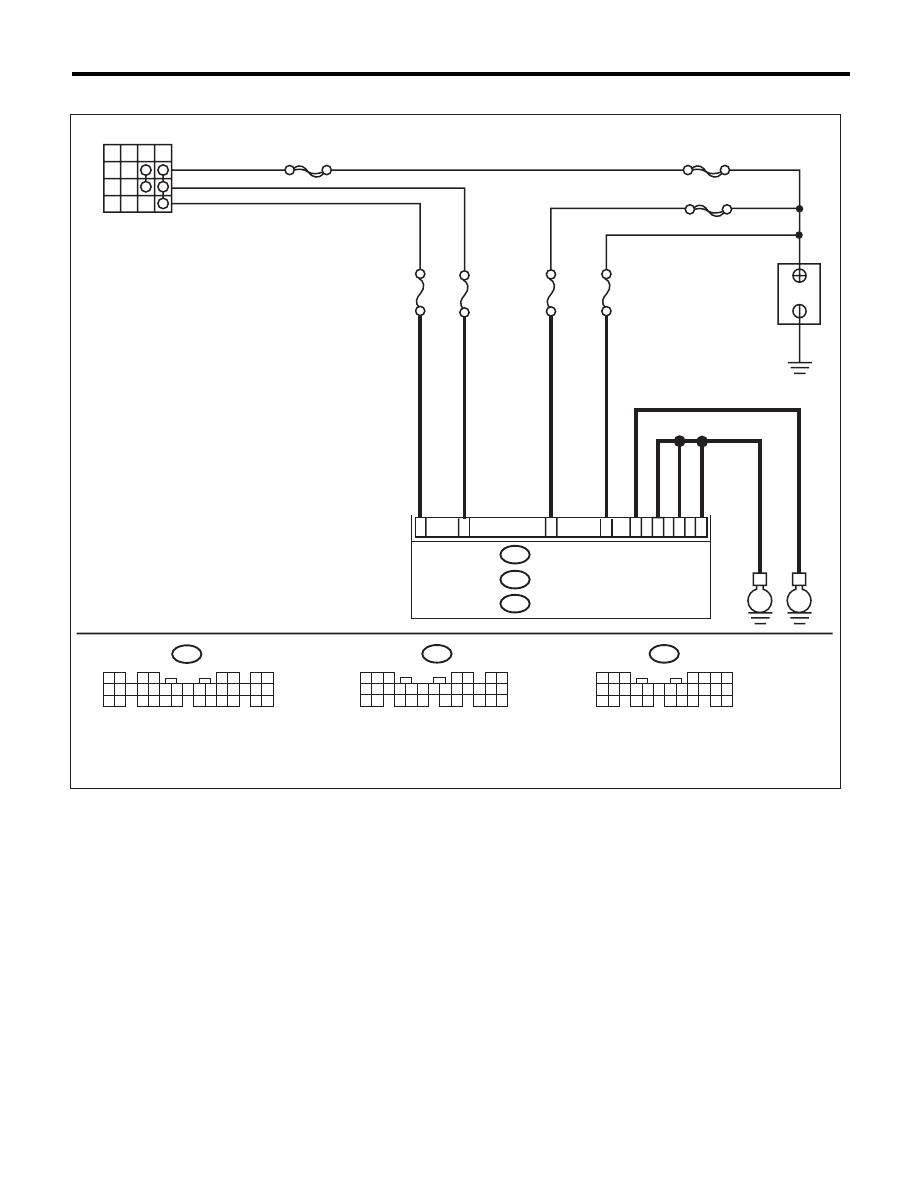
2. BODY INTEGRATED UNIT POWER SUPPLY AND GROUND CIRCUIT
5 6 7
8
2
1
9
4
3
10
24
22 23
25
11 12 13 14 15
26
27 28
16 17 18 19
20 21
5
4
6 7
8
2
1
9
3
10
22
23
11 12 13 14 15
24 25
26 27
16 17 18
28 29
19 20
21
30
1 2
3 4
5 6
7 8
9 10 11 12 13 14 15 16 17 18 19 20 21 22 23
24 25
26 27 28 29
30 31 32 33
34 35
B281
C:
B280
B:
i84
A:
OFF ACC
ACC
ON
B
IG
MAIN SBF
SBF-6
No.
12
No.
14
B281
C:
B280
B:
i84
A:
A1
C2
C8
C9
A21
B22
E
E
CS-00982
No.
31
A24
SBF-8
No.
7
C1
IGNITION SWITCH
B
A
TTER
Y
BODY INTEGRATED UNIT

CS-16
AT Shift Lock Control System
CONTROL SYSTEMS
Step
Check
Yes
No
1
CHECK DTC OF BODY INTEGRATED UNIT.
Check DTC of the body integrated unit.
<Ref. to LAN(diag)-12, OPERATION, Subaru
Select Monitor.>
Is the DTC of power line dis-
played on body integrated unit?
Repair or replace it
according to the
DTC.
Go to step 2.
2
CHECK HARNESS CONNECTOR BETWEEN
BODY INTEGRATED UNIT AND CHASSIS
GROUND.
1) Turn the ignition switch to ON.
2) Measure the voltage between the body inte-
grated unit and chassis ground.
Connector & terminal
(B281) No. 2 (+) — Chassis ground (–):
(B281) No. 1 (+) — Chassis ground (–):
(i84) No. 1 (+) — Chassis ground (–):
(i84) No. 24 (+) — Chassis ground (–):
Is the voltage 9 — 16 V?
Go to step 3.
Repair harness for
open circuit
between the body
integrated unit and
the battery or a
blown fuse.
3
CHECK HARNESS CONNECTOR BETWEEN
BODY INTEGRATED UNIT AND CHASSIS
GROUND.
1) Turn the ignition switch to OFF.
2) Measure the resistance of the harness
between the body integrated unit and chassis
ground.
Connector & terminal
(i84) No. 21 — Chassis ground:
(B280) No. 22 — Chassis ground:
(B281) No. 8 — Chassis ground:
(B281) No. 9 — Chassis ground:
Is the resistance less than 1
:? Go to step 4.
Repair the open
circuit of harness
between the body
integrated unit and
chassis ground.
4
CHECK POOR CONTACT.
Is there poor contact in connec-
tor?
Repair the poor
contact.
Check the body
integrated unit.
CS-17
AT Shift Lock Control System
CONTROL SYSTEMS
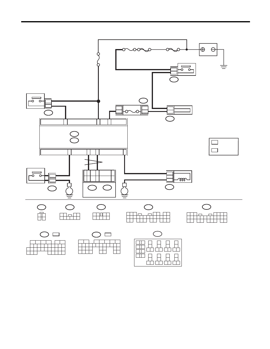
3. SELECT LEVER CANNOT BE LOCKED OR RELEASED
B281
C:
F :
F :
MAIN SBF
SBF-2
No. 8
E
B281
C:
B280
B:
C
23
B6
B159
B116
4
3
3
2
B65
B116
1
2
3
4
B65
1 2
3 4
5 6 7 8 9 10
5 6 7
8
2
1
9
4
3
10
24
22 23
25
11 12 13 14 15
26
27 28
16 17 18 19
20 21
1 2
3 4
5 6 7 8 9
B159
C1
No.
14
5
4
6 7
8
2
1
9
3
10
22
23
11 12 13 14 15
24 25
26 27
16 17 18
28 29
19 20
21
30
B280
B:
7.5A
3
B225
B225
4
C7
B350
4
3
5A
T
B30
B20
TCM
B54
B20
B21
5AT
16
10 11 12 13 14 15
25
24
30
9
8
7
17 18 19 20
28
21 22 23
29
32
31
1
2
3
4
5
6
27
26
33 34 35
B54
4A
T
A17
A18
B:
A:
B55
5
6
7
8
2
1
9
4
3
10
24
22 23
25
11 12 13 14 15
26 27
28
16 17 18 19
20 21
29 30 31
32 33
34 35
B55
A:
B:
E
C13
B116
1
2
CS-00965
13
14
15 16
17
27
24
25
26
20
21
22
23
29
30
31
28
32
35
33
34
37
38
39
36
40
8
9
10
11 12
1
2
5
3
4
7
6
19
18
F9
F5
: 4AT
: 5AT
BATTERY
STOP LIGHT SWITCH
FUSE & RELAY BOX
FUSE
(RELAY BLOCK)
: 4 SPEED AT
KEY WARNING SWITCH
BODY INTEGRATED UNIT
SHIFT LOCK SOLENOID
P RANGE SWITCH
: 5 SPEED AT
4AT

CS-18
AT Shift Lock Control System
CONTROL SYSTEMS
Step
Check
Yes
No
1
CHECK BODY INTEGRATED UNIT POWER
SUPPLY AND GROUND CIRCUIT.
<Ref. to CS-15, BODY INTEGRATED UNIT
POWER SUPPLY AND GROUND CIRCUIT,
INSPECTION, AT Shift Lock Control System.>
Is there an abnormal condition? Follow the proce-
dures to perform
inspection and
repair.
Go to step 2.
2
CHECK CURRENT DATA.
1) Connect the Subaru Select Monitor.
2) Shift the select lever to the “P” range.
3) Turn the ignition switch to ON.
4) Display the current data display and display
“P SW”. <Ref. to LAN(diag)-12, OPERATION,
Subaru Select Monitor.>
Is the display “ON” in the P
range and “OFF” in ranges
other than P?
Go to step 3.
Go to step 8.
3
CHECK CURRENT DATA.
Display the current data display and display
“Stop Light Switch”. <Ref. to LAN(diag)-12,
OPERATION, Subaru Select Monitor.>
Is “ON” displayed when the
brake pedal is depressed and
“OFF” displayed when the
brake pedal is released?
Go to step 4.
Go to step 11.
4
CHECK BODY INTEGRATED UNIT DTC.
Check the DTC of the body integrated unit when
the brake pedal is pressed and when it is
released.
(Hold each condition for 5 seconds or more.)
Is there a DTC of a current mal-
function?
Follow the DTC to
perform inspection
and repair.
Go to step 5.
5
CHECK CURRENT DATA.
Select the current data display and display
“Shift Lock Solenoid”. <Ref. to LAN(diag)-12,
OPERATION, Subaru Select Monitor.>
Is “ON” displayed when the
brake pedal is depressed and
“OFF” displayed when the
brake pedal is released?
Go to step 6.
Replace the body
integrated unit.
6
CHECK CURRENT DATA.
Select the current data display and display
“Shift Position”. <Ref. to LAN(diag)-12, OPER-
ATION, Subaru Select Monitor.>
Is the display “7” in the P range
and other than “7” in ranges
other than P?
Go to step 7.
Check the follow-
ing items.
• Inhibitor switch
• Harness
between inhibitor
switch and TCM
• TCM input signal
• TCM CAN com-
munication
• Body integrated
unit CAN receive
7
CHECK CURRENT DATA.
1) Select the current data display and display
“Front Wheel Speed”. <Ref. to LAN(diag)-12,
OPERATION, Subaru Select Monitor.>
2) Start the engine.
3) Raise vehicle speed gradually up to approx-
imately 20 km/h.
Is a figure equivalent to the
speedometer being indicated?
Go to step 12.
Check the follow-
ing items.
• Wheel speed
sensor
• VDC/ABS CAN
communication
• Body integrated
unit CAN receive
Replace the wheel
speed sensor,
VDC/ABS, or body
integrated unit, or
both.
Нет комментариевНе стесняйтесь поделиться с нами вашим ценным мнением.
Текст