Subaru Legacy IV (2008 year). Service manual — part 481
ME(H6DO)-50
Timing Chain Assembly
MECHANICAL
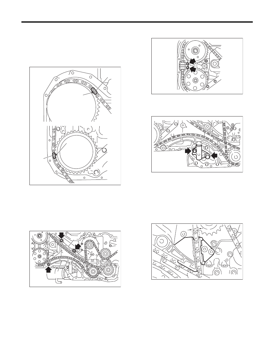
(2) Install the timing chain (RH) to the intake
cam sprocket (RH) and exhaust cam sprocket
(RH) in this order.
NOTE:
Check that the mark on timing chain (A) and cam
sprocket (B) is aligned as same as aligned on crank
sprocket.
(3) Install the chain guide (RH).
(4) Install the chain tensioner lever (RH).
Tightening torque:
16 N·m (1.6 kgf-m, 11.8 ft-lb)
(5) Install the chain guide (RH: between cams).
Tightening torque:
6.4 N·m (0.7 kgf-m, 4.7 ft-lb)
NOTE:
Use a new installing bolt.
(6) Install the chain tensioner (RH).
Tightening torque:
16 N·m (1.6 kgf-m, 11.8 ft-lb)
(7) Adjust the clearance between chain guide
(RH) and chain guide (center) within 8.4 — 8.6
mm (0.331 — 0.339 in). Install the chain guide
(center).
Tightening torque:
7.8 N·m (0.8 kgf-m, 5.9 ft-lb)
NOTE:
Use a new installing bolt.
(8) Check that each mark on the sprocket and
timing chain is matched, and then draw out the
stopper pin from chain tensioner.
9) Install the front chain cover. <Ref. to ME(H6DO)-
44, INSTALLATION, Front Chain Cover.>
10) Install the crank pulley. <Ref. to ME(H6DO)-43,
INSTALLATION, Crank Pulley.>
11) Install the V-belts. <Ref. to ME(H6DO)-42, IN-
STALLATION, V-belt.>
(A) Gold
(B) Mark
(A) Chain guide (RH)
(B) Chain tensioner lever (RH)
(A)
(A)
(B)
(B)
ME-02044
ME-02033
(A)
(B)
ME-02032
ME-00520
ME-00521
ME(H6DO)-51
Cam Sprocket
MECHANICAL
16.Cam Sprocket
A: REMOVAL
NOTE:
When replacing the single part, perform the work
with the engine installed to body.
1) Remove the V-belts. <Ref. to ME(H6DO)-42,
REMOVAL, V-belt.>
2) Remove the crank pulley. <Ref. to ME(H6DO)-
43, REMOVAL, Crank Pulley.>
3) Remove the front chain cover. <Ref. to
ME(H6DO)-44, REMOVAL, Front Chain Cover.>
4) Remove the timing chain assembly. <Ref. to
ME(H6DO)-46, REMOVAL, Timing Chain Assem-
bly.>
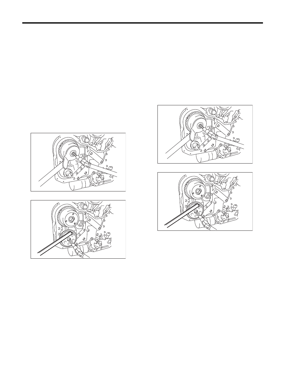
5) Remove the cam sprocket. To lock the cam-
shaft, use the ST.
ST
499977500
CAM SPROCKET WRENCH
ST
18231AA020
CAM SPROCKET WRENCH
B: INSTALLATION
1) Install the cam sprocket. To lock the camshaft,
use the ST.
Tightening torque:
29.5 N·m (3.0 kgf-m, 21.8 ft-lb)
2) Further tighten the bolts.
Tightening angle:
Intake side
45°
r
5°
Exhaust side
25°
r
5°
ST
499977500
CAM SPROCKET WRENCH
ST
18231AA020
CAM SPROCKET WRENCH
3) Install the timing chain assembly. <Ref. to
ME(H6DO)-47, INSTALLATION, Timing Chain As-
sembly.>
4) Install the front chain cover. <Ref. to ME(H6DO)-
44, INSTALLATION, Front Chain Cover.>
5) Install the crank pulley. <Ref. to ME(H6DO)-43,
INSTALLATION, Crank Pulley.>
6) Install the V-belts. <Ref. to ME(H6DO)-42, IN-
STALLATION, V-belt.>
C: INSPECTION
1) Check the cam sprocket teeth for abnormal wear
and scratches.
2) Make sure there is no free play between cam
sprocket and key.
ME-02045
ME-02046
ME-02045
ME-02046
ME(H6DO)-52
Crank Sprocket
MECHANICAL
17.Crank Sprocket
A: REMOVAL
NOTE:
When replacing the single part, perform the work
with the engine installed to body.
1) Remove the V-belts. <Ref. to ME(H6DO)-42,
REMOVAL, V-belt.>
2) Remove the crank pulley. <Ref. to ME(H6DO)-
43, REMOVAL, Crank Pulley.>
3) Remove the front chain cover. <Ref. to
ME(H6DO)-44, REMOVAL, Front Chain Cover.>
4) Remove the timing chain assembly. <Ref. to
ME(H6DO)-46, REMOVAL, Timing Chain Assem-
bly.>
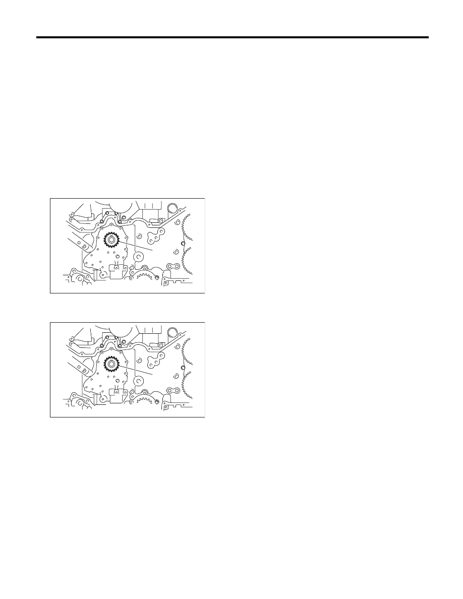
5) Remove the crank sprocket (A).
B: INSTALLATION
1) Install the crank sprocket (A).
2) Install the timing chain assembly. <Ref. to
ME(H6DO)-47, INSTALLATION, Timing Chain As-
sembly.>
3) Install the front chain cover. <Ref. to ME(H6DO)-
44, INSTALLATION, Front Chain Cover.>
4) Install the crank pulley. <Ref. to ME(H6DO)-43,
INSTALLATION, Crank Pulley.>
5) Install the V-belts. <Ref. to ME(H6DO)-42, IN-
STALLATION, V-belt.>
C: INSPECTION
1) Check the crank sprocket teeth for abnormal
wear and scratches.
2) Make sure there is no free play between crank
sprocket and key.
ME-02047
(A)
ME-02047
(A)
ME(H6DO)-53
Rear Chain Cover
MECHANICAL
18.Rear Chain Cover
A: REMOVAL
NOTE:
When replacing the single part, perform the work
with the engine installed to body.
1) Remove the V-belts. <Ref. to ME(H6DO)-42,
REMOVAL, V-belt.>
2) Remove the crank pulley. <Ref. to ME(H6DO)-
43, REMOVAL, Crank Pulley.>
3) Remove the front chain cover. <Ref. to
ME(H6DO)-44, REMOVAL, Front Chain Cover.>
4) Remove the timing chain. <Ref. to ME(H6DO)-
46, REMOVAL, Timing Chain Assembly.>
5) Remove the cam sprocket. <Ref. to ME(H6DO)-
51, REMOVAL, Cam Sprocket.>
6) Remove the crank sprocket. <Ref. to
ME(H6DO)-52, REMOVAL, Crank Sprocket.>
7) Remove the oil pump. <Ref. to LU(H6DO)-9,
REMOVAL, Oil Pump.>
8) Remove the water pump. <Ref. to CO(H6DO)-
12, REMOVAL, Water Pump.>
9) Remove the rear chain cover.
NOTE:
Installation bolt has seven different sizes. To pre-
vent the confusion in installation, keep these bolts
on container individually.
B: INSTALLATION
NOTE:
When replacing the rear chain cover, it is required
to select the size. <Ref. to LU(H6DO)-10, INSPEC-
TION, Oil Pump.>
1) Remove the used liquid gasket from mating sur-
face, and degrease it.
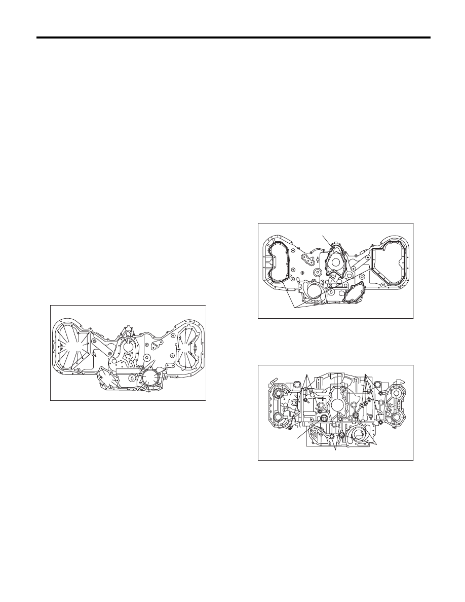
2) Apply liquid gasket to the mating surface of rear
chain cover.
NOTE:
Install within 5 minutes after applying liquid gasket.
Liquid gasket:
THREE BOND 1217G (Part No. K0877Y0100)
or equivalent
Applying liquid gasket diameter
(A) 1.0
r
0.5 mm (0.039
r
0.020 in)
(B) 3.0
r
1.0 mm (0.118
r
0.039 in)
3) Install the O-ring.
NOTE:
• Use new O-rings.
• Do not install the O-ring in wrong place.
4) Install the water pump gasket.
NOTE:
Use a new gasket.
(A) M6 × 14
(B) M6 × 18 (Silver)
(C) M6 × 30
(D) M6 × 18
(E) M8 × 40
(F) M8 × 30
(G) M6 × 22
ME-02048
(F)
(C)
(D)
(E)
(G)
(A) (B)
(A) 14.2 × 1.9
(B) 19.2 × 2.4
(C) 25 × 2
(D) 31.2 × 1.9
(A)
(B)
ME-02049
(B)
(D)
(C)
(A)
(A)
ME-02457
Нет комментариевНе стесняйтесь поделиться с нами вашим ценным мнением.
Текст