Subaru Legacy IV (2008 year). Service manual — part 479
ME(H6DO)-42
V-belt
MECHANICAL
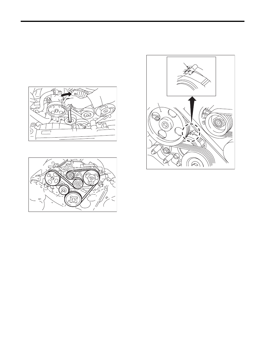
12.V-belt
A: REMOVAL
NOTE:
Perform the work with the engine installed to body
when replacing a single part.
1) Remove the collector cover.
2) Install the tool to belt tension adjuster assembly
installation bolt.
3) Rotate the tool clockwise and loosen the V-belt
to remove.
B: INSTALLATION
Install in the reverse order of removal.
C: INSPECTION
1) Replace the V-belt, if cracks, fraying or wear is
found.
2) Make sure that the V-belt automatic belt tension
indicator (A) is within the range (D).
(1) Power steering oil pump pulley
(2) Belt tension adjuster ASSY
(3) Crank pulley
(4) A/C compressor pulley
(5) Belt idler
(6) Generator pulley
ME-00473
(1)
(6)
(4)
(5)
(2)
(3)
ME-00474
(A) Indicator
(B) Generator
(C) Power steering oil pump pulley
(D) Service limit
(B)
(A)
(D)
(C)
ME-00475
ME(H6DO)-43
Crank Pulley
MECHANICAL
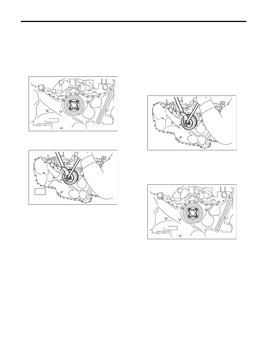
13.Crank Pulley
A: REMOVAL
NOTE:
Perform the work with the engine installed to body
when replacing a single part.
1) Remove the V-belts. <Ref. to ME(H6DO)-42,
REMOVAL, V-belt.>
2) Remove the crank pulley cover.
3) Remove the crank pulley bolt. To lock the crank-
shaft, use ST.
ST
499977100
CRANK PULLEY WRENCH
4) Remove the crank pulley.
B: INSTALLATION
1) Install the crank pulley.
2) Install the crank pulley bolt. To lock the crank-
shaft, use ST.
ST
499977100
CRANK PULLEY WRENCH
(1) Clean the crankshaft thread using com-
pressed air.
(2) Apply engine oil to the crank pulley bolt seat
and thread.
(3) Tighten the crank pulley bolts.
Tightening torque:
178 N·m (18.1 kgf-m, 131.3 ft-lb)
3) Install the crank pulley cover.
NOTE:
Use new O-rings.
Tightening torque:
6.4 N·m (0.7 kgf-m, 4.7 ft-lb)
4) Install the V-belts. <Ref. to ME(H6DO)-42, IN-
STALLATION, V-belt.>
C: INSPECTION
1) Check the crank pulley cover for oil and air leak-
age.
2) Check the crank pulley for looseness.
ME-02028
ME-02598
ST
ME-00497
ME-02028
ME(H6DO)-44
Front Chain Cover
MECHANICAL
14.Front Chain Cover
A: REMOVAL
NOTE:
When replacing the single part, perform the work
with the engine installed to body.
1) Remove the V-belts. <Ref. to ME(H6DO)-42,
REMOVAL, V-belt.>
2) Remove the crank pulley. <Ref. to ME(H6DO)-
43, REMOVAL, Crank Pulley.>
3) Remove the bolts which install oil pipe (RH) onto
the front chain cover.
4) Remove the front chain cover.
NOTE:
Chain cover installation bolt has three different siz-
es. To prevent the confusion in installation, keep
these bolts on container individually.
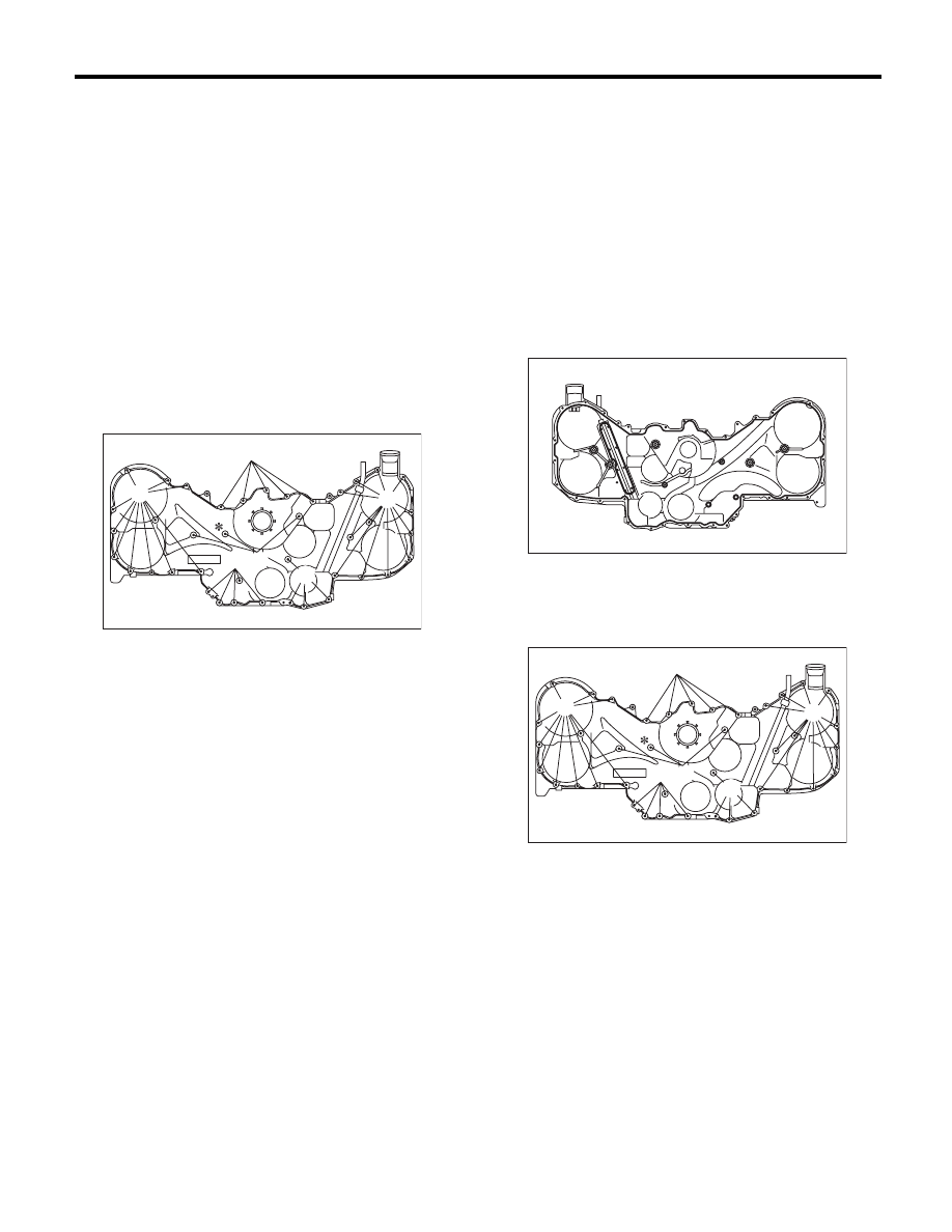
B: INSTALLATION
1) Remove the used liquid gasket from mating sur-
face, and degrease it.
2) Apply liquid gasket to the mating surface of front
chain cover.
NOTE:
Install within 5 minutes after applying liquid gasket.
Liquid gasket:
THREE BOND 1217G (Part No. K0877Y0100)
or equivalent
Applying liquid gasket diameter
2.5
r
0.5 mm (0.098
r
0.020 in)
3) Install the front chain cover. Temporarily tighten
the bolts.
CAUTION:
Do not install the bolts in wrong place.
(A) M6 × 16
(B) M6 × 30
(C) M6 × 45
*: Sealing washer
(C)
(C)
(A)
(B)
(B)
ME-02029
(A)
(A) M6 × 16
(B) M6 × 30
(C) M6 × 45
*: Sealing washer
ME-02385
(C)
(C)
(A)
(B)
(B)
ME-02029
(A)
ME(H6DO)-45
Front Chain Cover
MECHANICAL
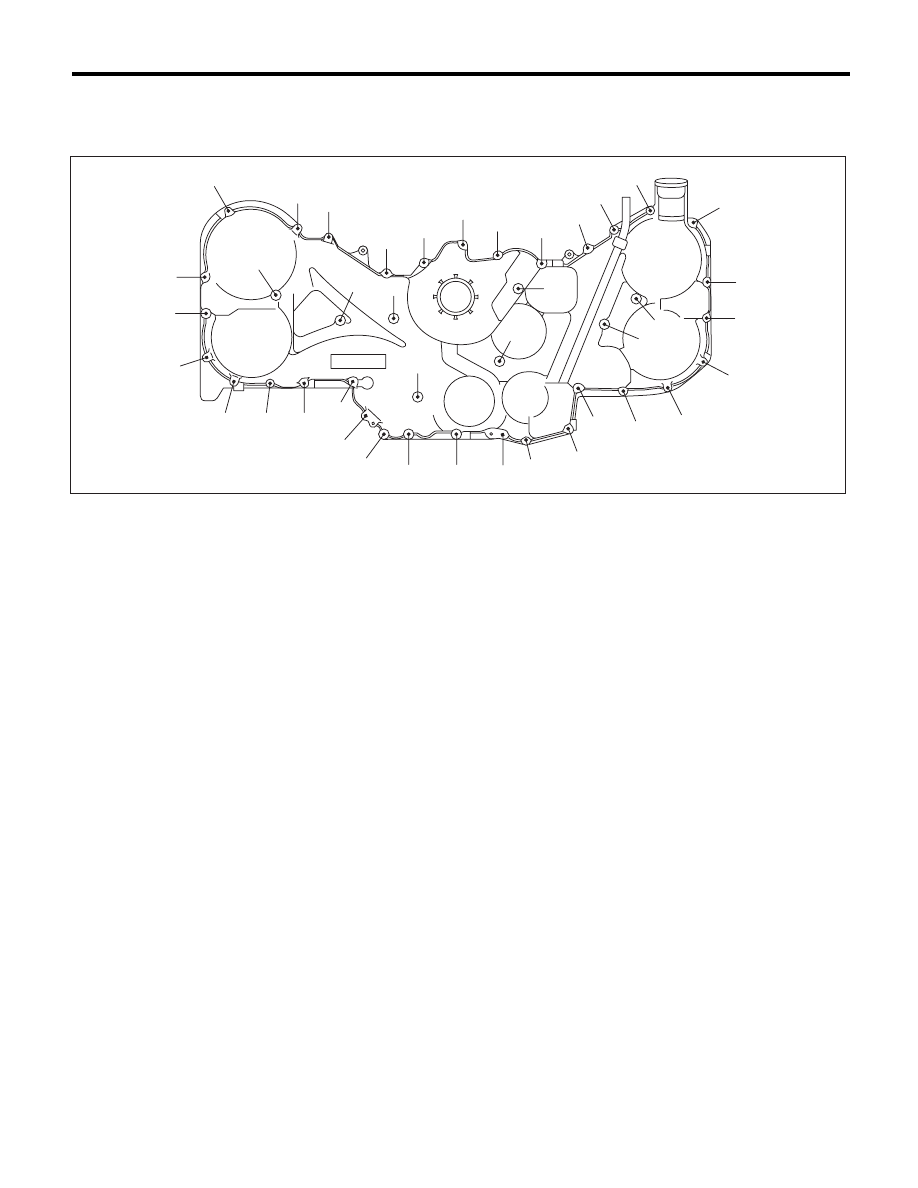
4) Tighten the bolts in the numerical order as shown in the figure.
Tightening torque:
6.6 N·m (0.7 kgf-m, 4.9 ft-lb)
5) Tighten the bolts which install oil pipe (RH) onto
the front chain cover.
Tightening torque:
6.4 N·m (0.7 kgf-m, 4.7 ft-lb)
6) Install the crank pulley. <Ref. to ME(H6DO)-43,
INSTALLATION, Crank Pulley.>
7) Install the V-belts. <Ref. to ME(H6DO)-42, IN-
STALLATION, V-belt.>
C: INSPECTION
Check the cover surface for scratch and damage.
Check for oil leakage on cover mating surface and
installation part of crank pulley.
ME-02031
(21)
(22)
(40)
(39)
(38)
(37)
(36)
(35)
(34)
(33)
(32)
(13)
(12)
(11)
(9)
(10)
(23)
(24)
(8)
(6)
(25)
(26)
(27)
(28)
(29)
(30)
(31)
(19)
(18)
(17)
(16)
(15)
(14)
(20)
(3)
(2)
(4)
(5)
(1)
(7)
Нет комментариевНе стесняйтесь поделиться с нами вашим ценным мнением.
Текст