Subaru Legacy IV (2008 year). Service manual — part 254
IN(H4DOTC)-13
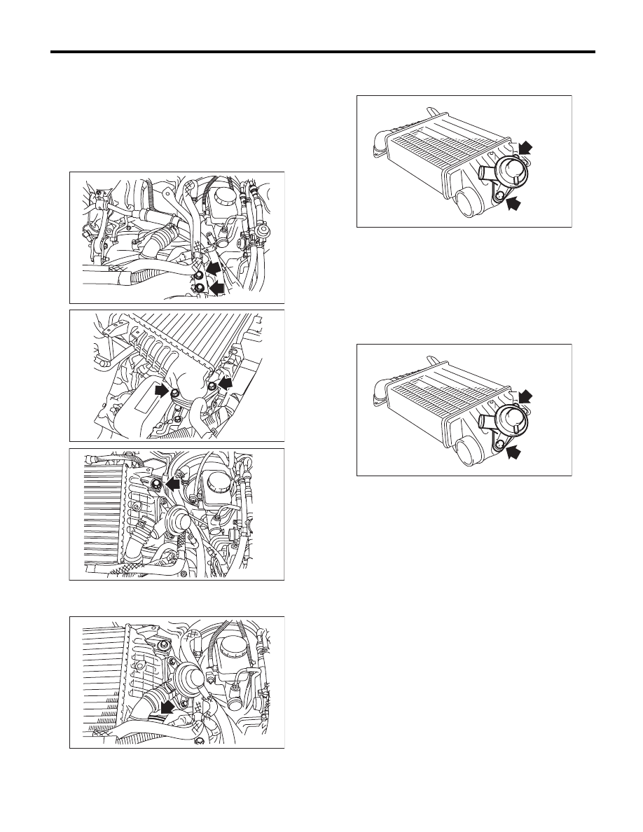
Intercooler
INTAKE (INDUCTION)
B: INSTALLATION
Install in the reverse order of removal.
NOTE:
• Use new O-rings.
• Be careful not to pinch the O-ring.
Tightening torque:
16 N·m (1.6 kgf-m, 11.8 ft-lb)
Tightening torque:
3 N·m (0.3 kgf-m, 2.2 ft-lb)
C: DISASSEMBLY
1) Remove the air by-pass valve from intercooler.
D: ASSEMBLY
Assemble in the reverse order of disassembly.
NOTE:
• Use new O-rings.
• Be careful not to pinch the O-ring.
Tightening torque:
6.5 N·m (0.7 kgf-m, 4.8 ft-lb)
E: INSPECTION
Check for cracks or loose connections.
IN-02303
IN-02467
IN-02468
IN-02304
IN-02094
IN-02094
IN(H4DOTC)-14
Turbocharger
INTAKE (INDUCTION)
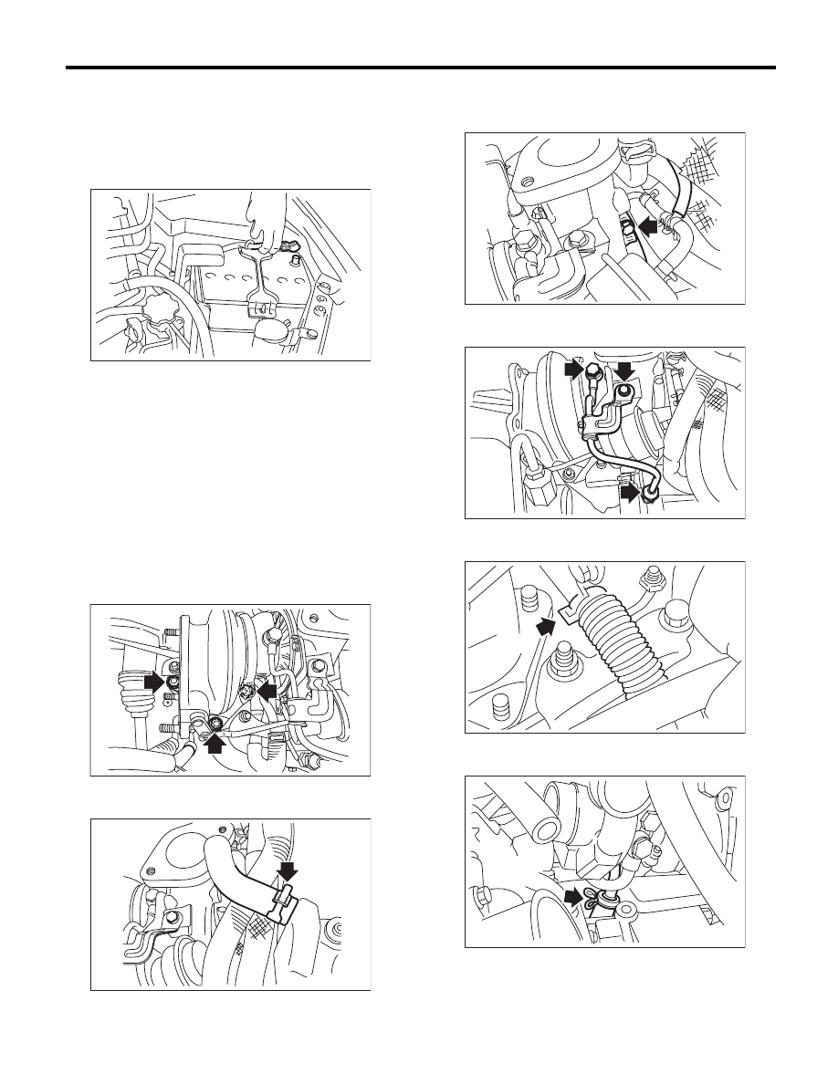
8. Turbocharger
A: REMOVAL
1) Set the vehicle on a lift.
2) Remove the collector cover.
3) Disconnect the ground cable from battery.
4) Lift up the vehicle.
5) Drain approximately 3.0
2 (3.2 US qt, 2.6 Imp
qt) of coolant. <Ref. to CO(H4DOTC)-14, DRAIN-
ING OF ENGINE COOLANT, REPLACEMENT,
Engine Coolant.>
6) Lower the vehicle.
7) Remove the intercooler. <Ref. to IN(H4DOTC)-
12, REMOVAL, Intercooler.>
8) Remove the center exhaust pipe. <Ref. to
EX(H4DOTC)-7, REMOVAL, Center Exhaust
Pipe.>
9) Lower the vehicle.
10) Separate the turbocharger joint pipe from tur-
bocharger.
11) Disconnect the engine coolant hose which is
connected to coolant filler tank.
12) Disconnect the air control hose (A), and loosen
the clamp holding the turbocharger to the intake
duct.
13) Remove the oil inlet pipe from the turbocharg-
er.
14) Disconnect the engine coolant hose from the
water pipe.
15) Disconnect the oil outlet hose from the oil outlet
pipe.
16) Take out the turbocharger from engine com-
partment.
IN-00203
IN-02497
IN-02506
(A)
IN-02499
IN-02500
IN-02456
IN-02310
IN(H4DOTC)-15
Turbocharger
INTAKE (INDUCTION)
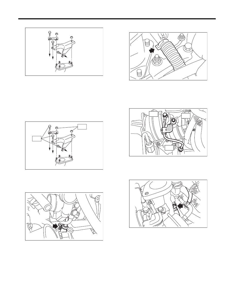
17) Remove the turbocharger stay.
B: INSTALLATION
1) Install the turbocharger stay.
Tightening torque:
T1: 33 N·m (3.4 kgf-m, 24.3 ft-lb)
T2: 42.5 N·m (4.3 kgf-m, 31.3 ft-lb)
2) Connect the oil outlet hose to the oil outlet pipe.
3) Connect the engine coolant hoses to the water
pipe.
4) Install the oil inlet pipe to turbocharger.
Tightening torque:
T1: 5 N·m (0.5 kgf-m, 3.7 ft-lb)
T2: 16 N·m (1.6 kgf-m, 11.8 ft-lb)
T3: 20 N·m (2.0 kgf-m, 14.8 ft-lb)
5) Connect the air control hose (A) and install the
turbocharger to the intake duct.
Tightening torque:
3 N·m (0.3 kgf-m, 2.2 ft-lb)
(A) To cylinder head RH
(B) To cylinder block RH
(A) To cylinder head RH
(B) To cylinder block RH
IN-02373
(A)
(A)
(B)
IN-02377
(A)
(A)
(B)
T2
T1
IN-02310
IN-02456
IN-02501
T1
T2
T3
(A)
IN-02499
IN(H4DOTC)-16
Turbocharger
INTAKE (INDUCTION)
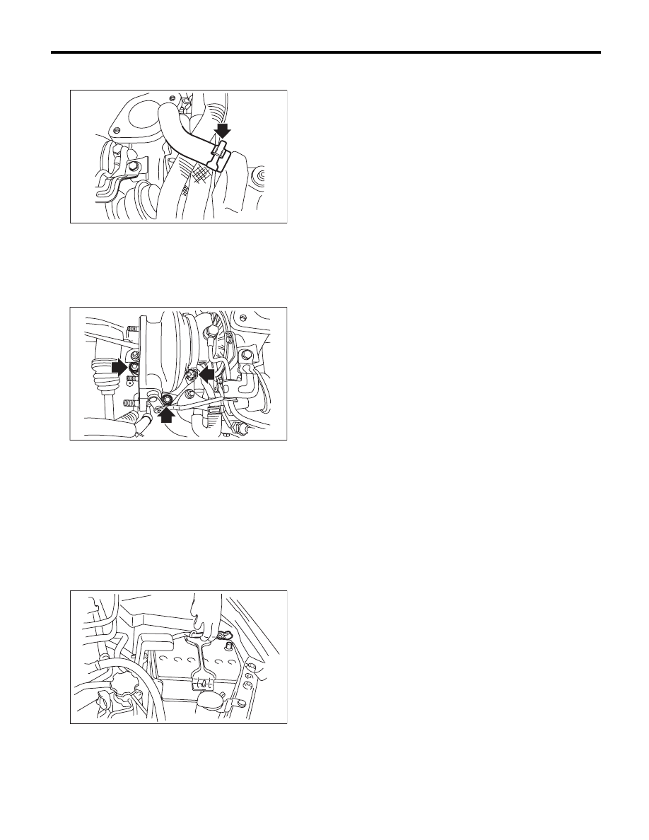
6) Connect the engine coolant hose which is con-
nected to the coolant filler tank.
7) Install the joint pipe to turbocharger.
NOTE:
Replace the gasket with a new part.
Tightening torque:
42.5 N·m (4.3 kgf-m, 31.3 ft-lb)
8) Lift up the vehicle.
9) Install the center exhaust pipe. <Ref. to
EX(H4DOTC)-9, INSTALLATION, Center Exhaust
Pipe.>
10) Lower the vehicle.
11) Install the intercooler. <Ref. to IN(H4DOTC)-
13, INSTALLATION, Intercooler.>
12) Fill engine coolant. <Ref. to CO(H4DOTC)-14,
FILLING OF ENGINE COOLANT, REPLACE-
MENT, Engine Coolant.>
13) Connect the ground cable to battery.
14) Install the collector cover.
C: INSPECTION
• Check that there are no oil leaks or water leaks
from the pipe attachment section.
• Check for cracks or loose connections.
IN-02506
IN-02497
IN-00203
Нет комментариевНе стесняйтесь поделиться с нами вашим ценным мнением.
Текст