Subaru Legacy IV (2008 year). Service manual — part 688
4AT-100
Front Differential Assembly
AUTOMATIC TRANSMISSION
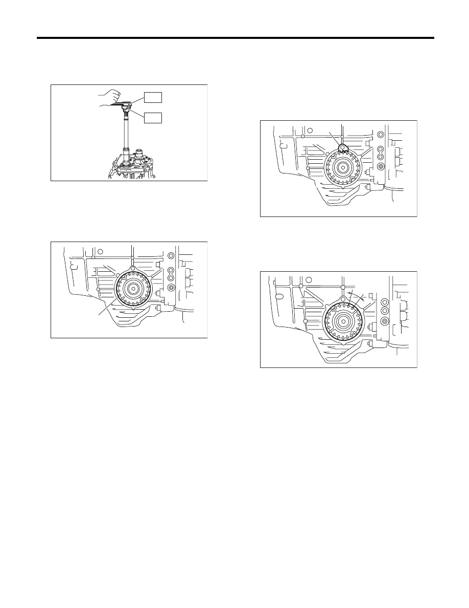
5) Rotate the drive pinion a few times using ST1
and ST2.
ST1
498937110
HOLDER
ST2
499787700
WRENCH
6) Tighten the LH differential side retainer by rotat-
ing the shaft until resistance is felt. Then loosen the
RH side differential side retainer. Tighten the LH
differential side retainer until the pinion shaft no
longer turns, and continue to loosen the RH side.
This is the “zero” state.
7) After reaching the “zero” state, loosen the LH dif-
ferential side retainer by 3 notches and secure it
with the lock plate. Then after returning the RH dif-
ferential side retainer, retighten until it stops. Ro-
tate the drive pinion 2 or 3 times. Tighten the RH
differential side retainer further by 1-3/4 notches.
This sets the preload. Finally, secure the differen-
tial side retainer with the lock plate.
NOTE:
Turning the differential side retainer by one notch
changes the backlash approx. 0.05 mm (0.0020 in).
8) Install the Subaru genuine axle shafts to the right
and left sides of the front differential.
Install the axle shaft to both sides of the front differ-
ential section.
Part No.
38415AA000
Axle shaft
(A) Differential side retainer
AT-00206
ST2
ST1
AT-00229
(A)
(A) Lock plate
AT-00214
(A)
0.05 mm
(0.0020 in)
AT-00230
4AT-101
Front Differential Assembly
AUTOMATIC TRANSMISSION
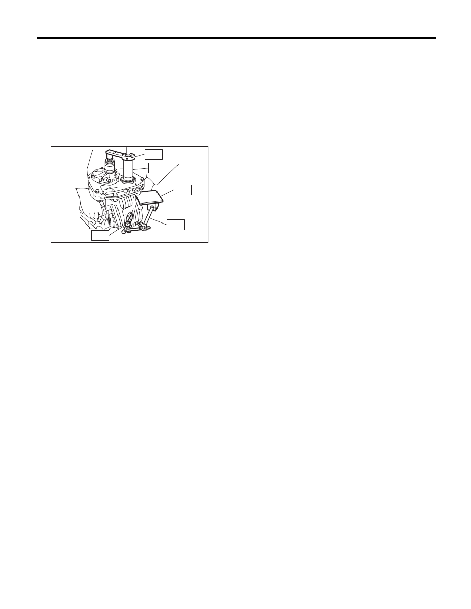
9) Turn the drive pinion several times using ST1,
and check to see if the backlash is within the spec-
ification using ST2, ST3, ST4 and ST5.
ST1
499787700
WRENCH
ST2
498247001
MAGNET BASE
ST3
498247100
DIAL GAUGE
ST4
499787500
ADAPTER
ST5
498255400
PLATE
Backlash:
0.13 — 0.18 mm (0.0051 — 0.0071 in)
10) Adjust the teeth contact of the front differential
and drive pinion shaft. <Ref. to 4AT-92, ADJUST-
MENT, Drive Pinion Shaft Assembly.>
AT-00231
ST5
ST3
ST2
ST1
ST4
4AT-102
AT Main Case
AUTOMATIC TRANSMISSION
34.AT Main Case
A: REMOVAL
1) Remove the transmission assembly from vehicle
body. <Ref. to 4AT-35, REMOVAL, Automatic
Transmission Assembly.>
2) Pull out the torque converter clutch assembly.
<Ref. to 4AT-67, REMOVAL, Torque Converter
Clutch Assembly.>
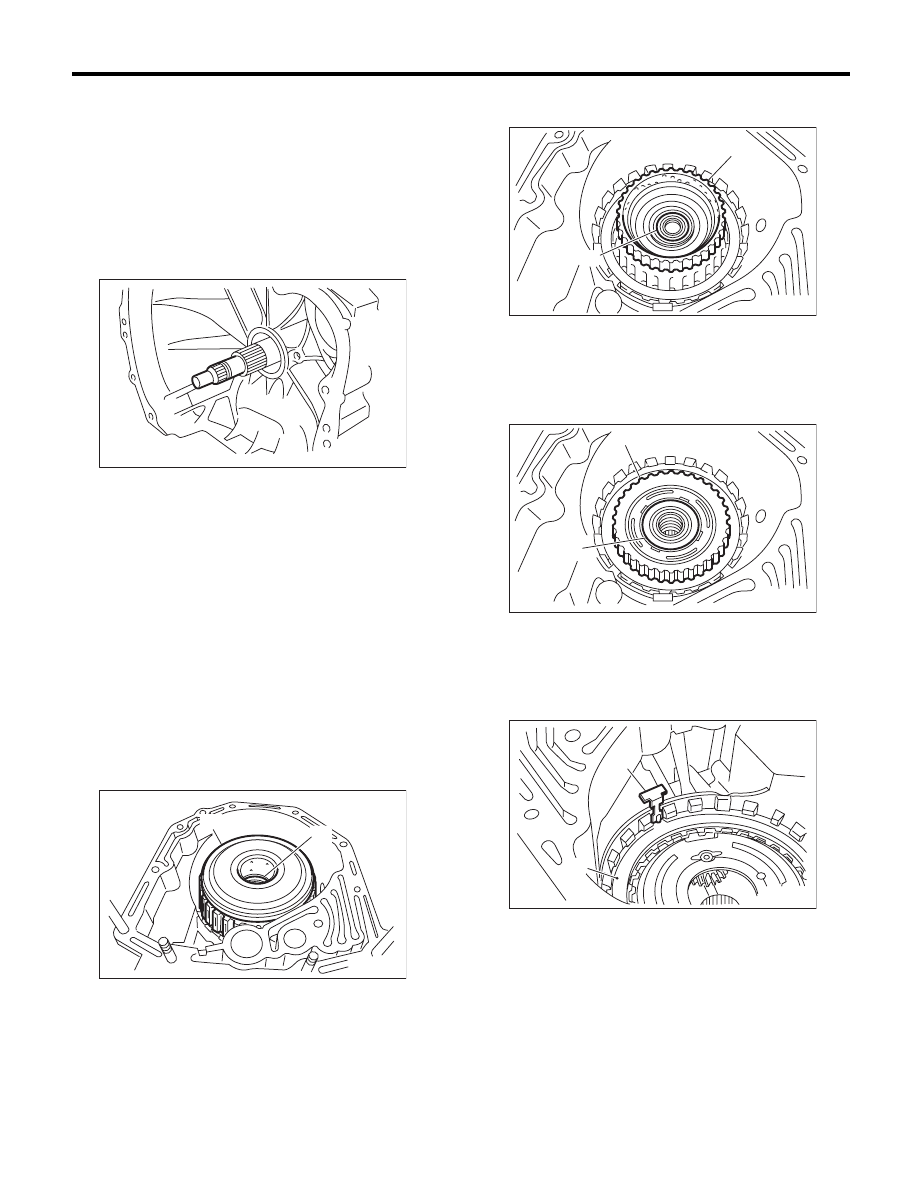
3) Remove the input shaft.
4) Lift up the lever on the rear side of transmission
harness connector, and then disconnect it from the
stay.
5) Disconnect the inhibitor switch connector from
the stay.
6) Disconnect the air breather hose.
7) Remove the oil charge pipe. <Ref. to 4AT-66,
REMOVAL, Oil Charge Pipe.>
8) Remove the ATF inlet and outlet pipes. <Ref. to
4AT-62, REMOVAL, ATF Cooler Pipe and Hose.>
9) Separate the converter case from the transmis-
sion case. <Ref. to 4AT-80, REMOVAL, Converter
Case.>
10) Remove the oil pump housing.
<Ref. to 4AT-83, REMOVAL, Oil Pump Housing.>
11) Take out the high clutch, thrust needle bearing
and reverse clutch assembly.
12) Take out the high clutch hub and thrust bear-
ing.
13) Take out the front sun gear and thrust needle
bearing.
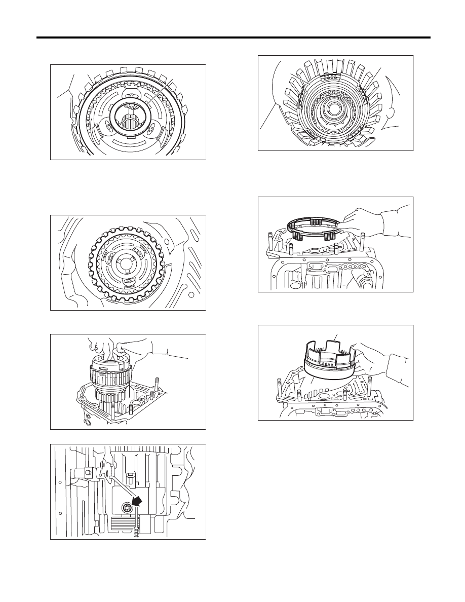
14) Pull out while being careful not to break the leaf
spring of the 2-4 brake.
(A) High clutch and reverse clutch ASSY
(B) Thrust needle bearing
AT-00114
AT-00232
(B)
(A)
(A) High clutch hub
(B) Thrust needle bearing
(A) Front sun gear
(B) Thrust needle bearing
(A) Leaf spring
(B) Retaining plate
AT-00233
(A)
(B)
AT-00251
(A)
(B)
AT-00252
(A)
(B)
4AT-103
AT Main Case
AUTOMATIC TRANSMISSION
15) Remove the snap ring and thrust needle bear-
ing.
16) Take out the retaining plate, drive plate and
driven plate of the 2-4 brake.
17) Take out the thrust needle bearing, planetary
gear assembly and low clutch assembly.
18) Remove the 2-4 brake seal.
19) Remove the snap ring.
20) Take out the 2-4 brake spring retainer.
21) Remove the 2-4 brake piston and 2-4 brake
piston retainer while taking care not to damage
them.
(A) Snap ring
(B) Thrust needle bearing
AT-00253
(A)
(B)
AT-00254
AT-00255
AT-04848
(A) Snap ring
(B) 2-4 brake piston
(A) 2-4 brake piston
(B) 2-4 brake piston retainer
AT-00285
(B)
(A)
AT-00286
AT-00287
(A)
(B)
Нет комментариевНе стесняйтесь поделиться с нами вашим ценным мнением.
Текст