Subaru Legacy IV (2008 year). Service manual — part 962
PS-10
General Description
POWER ASSISTED SYSTEM (POWER STEERING)
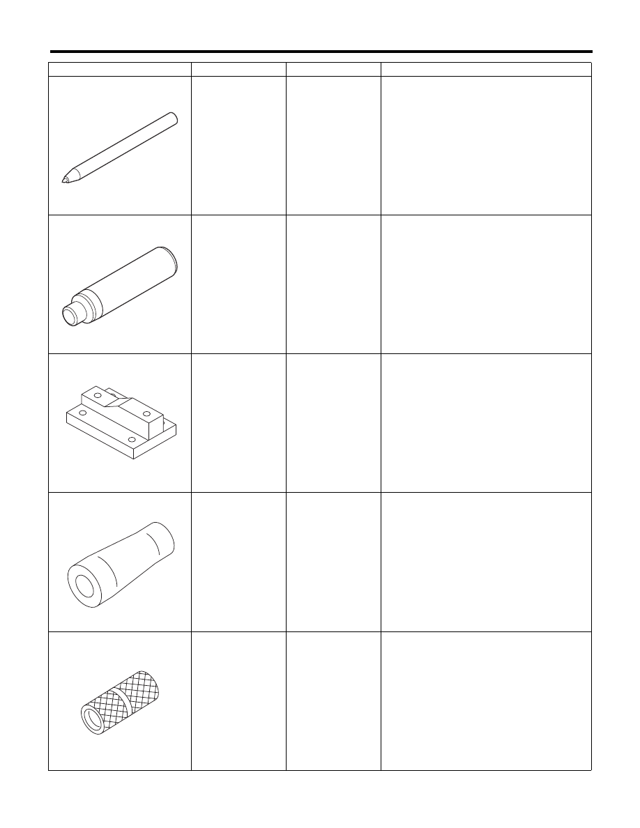
34099FA060
PUNCH HOLDER
Used for crimping.
34199FE000
INSTALLER &
REMOVER
Used for removing and installing the rack oil seal
(outer & inner).
34199AG000
BOSS D
• Used when inspecting characteristic of gear-
box assembly and disassembling it.
• Used together with STAND (926200000).
34199AG030
GUIDE
Used for installing seal ring of rack.
34199AG070
FORMER
Used for forming seal ring of pinion.
ILLUSTRATION
TOOL NUMBER
DESCRIPTION
REMARKS
ST34099FA060
ST34199FE000
ST34199AG000
ST34199AG030
ST34199AG070
PS-11
General Description
POWER ASSISTED SYSTEM (POWER STEERING)
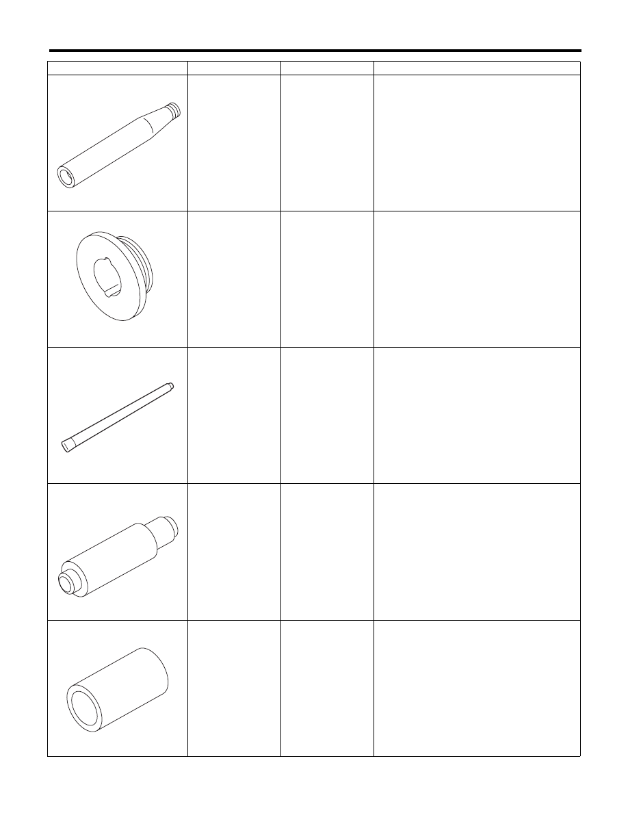
34199AG020
GUIDE
Used for installing seal ring of pinion.
34199AG050
GUIDE G (24)
• Used for forming seal ring of rack.
• Used together with FORMER PISTON
(34199AG080).
34099FA140
OIL SEAL
REMOVER
Used for removing oil seal.
34199AG090
INSTALLER &
REMOVER
• Used for installing oil seal of valve housing.
• Used together with the SEAL INSTALLER.
(34099FA130)
• Used for installing ball bearing of valve hous-
ing.
• Used for removing oil seal and ball bearing
from valve housing.
34199AG080
FORMER PISTON
• Used for forming seal ring of rack.
• Used together with the GUIDE G (24)
(34199AG050).
ILLUSTRATION
TOOL NUMBER
DESCRIPTION
REMARKS
ST34199AG020
ST34199AG050
ST34099FA140
ST34199AG090
ST34199AG080
PS-12
General Description
POWER ASSISTED SYSTEM (POWER STEERING)
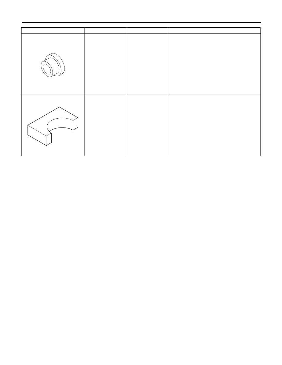
34199AG010
INSTALLER
Used for pressing-fit oil seal of gearbox cylinder.
34199FE020
BASE
Used for crimping.
ILLUSTRATION
TOOL NUMBER
DESCRIPTION
REMARKS
ST34199AG010
ST34199FE020
PS-13
Steering Wheel
POWER ASSISTED SYSTEM (POWER STEERING)
2. Steering Wheel
A: REMOVAL
1) Disconnect the ground cable from the battery.
2) Set the tire to the straight-ahead position.
3) Remove the airbag module. <Ref. to AB-14, RE-
MOVAL, Driver’s Airbag Module.>
WARNING:
Always refer to “Airbag System” before per-
forming service on the airbag modules. <Ref. to
AB-4, CAUTION, General Description.>
4) Place alignment marks on the steering wheel
and steering shaft.
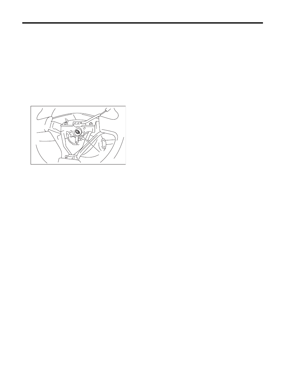
5) Remove the steering wheel nut, and then draw
out the steering wheel from shaft using steering
puller.
B: INSTALLATION
WARNING:
Always refer to “Airbag System” before per-
forming service on the airbag modules. <Ref. to
AB-4, CAUTION, General Description.>
1) Align the center position of the roll connector.
<Ref. to AB-25, ADJUSTMENT, Roll Connector.>
2) Install in the reverse order of removal.
NOTE:
Align the alignment marks on the steering wheel
and steering shaft.
Tightening torque:
39 N·m (4.0 kgf-m, 28.8 ft-lb)
Column cover-to-steering wheel clearance:
2 — 4 mm (0.08 — 0.16 in)
CAUTION:
Insert the roll connector guide pin into the
guide hole on the lower end of the steering
wheel surface. Avoid damaging the pin.
C: INSPECTION
1) Check the steering wheel for deformation. If the
deformation is excessive, replace the steering
wheel.
2) Check the splines on the steering wheel for dam-
age. If the damage is excessive, replace the steer-
ing wheel.
(1) Alignment mark
(1)
PS-00552
Нет комментариевНе стесняйтесь поделиться с нами вашим ценным мнением.
Текст