Subaru Legacy IV (2008 year). Service manual — part 773

5AT(diag)-107
Diagnostic Procedure without Diagnostic Trouble Code (DTC)
AUTOMATIC TRANSMISSION (DIAGNOSTICS)
5
CHECK DTC OF TCM.
Is DTC of CAN detected?
Perform the diag-
nosis according to
DTC.
Replace the TCM.
<Ref. to 5AT-60,
Transmission Con-
trol Module
(TCM).>
6
CHECK DTC OF METER.
Is DTC of CAN detected?
Perform the diag-
nosis according to
DTC.
Replace the meter.
7
CHECK GROUND CIRCUIT OF SPORT/MAN-
UAL MODE SWITCH.
1) Turn the ignition switch to OFF.
2) Disconnect the connector from SPORT/
manual mode switch.
3) Measure the resistance of harness between
SPORT/manual mode switch connector and
chassis ground.
Connector & terminal
(B116) No. 6 — Chassis ground:
(B116) No. 10 — Chassis ground:
Is the resistance less than 1
:? Go to step 8.
Repair the open
circuit of harness
between SPORT/
manual mode
switch and chassis
ground.
8
CHECK SPORT/MANUAL MODE SWITCH.
Measure the resistance between SPORT/man-
ual mode switch terminals.
Connector & terminal
(B116) No. 6 — No. 7:
(B116) No. 10 — No. 11:
Is the resistance 1 M
: or
more?
Go to step 9.
Replace the guide
plate assembly.
9
CHECK SPORT/MANUAL MODE SWITCH.
1) Move the select lever to manual mode.
2) Measure the resistance between SPORT/
manual mode switch terminals.
Connector & terminal
(B116) No. 6 — No. 7:
(B116) No. 10 — No. 11:
Is the resistance less than 1
:? Go to step 10.
Replace the guide
plate assembly.
10
CHECK HARNESS CONNECTOR BETWEEN
BODY INTEGRATED UNIT AND SPORT/
MANUAL MODE SWITCH.
1) Disconnect the connector from body inte-
grated unit.
2) Measure the resistance of harness between
body integrated unit connector and SPORT/
manual mode switch connector.
Connector & terminal
(B116) No. 7 — (B281) No. 15:
(B116) No. 11 — (B281) No. 25:
Is the resistance less than 1
:? Go to step 11.
Repair the open
circuit of harness
between the
SPORT/manual
mode switch con-
nector and body
integrated unit con-
nector, or poor
contact of connec-
tor.
11
CHECK HARNESS CONNECTOR BETWEEN
BODY INTEGRATED UNIT AND SPORT/
MANUAL MODE SWITCH.
1) Disconnect the connector from body inte-
grated unit.
2) Measure the resistance of harness between
SPORT/manual mode switch connector and
chassis ground.
Connector & terminal
(B116) No. 7 — Chassis ground:
(B116) No. 9 — Chassis ground:
Is the resistance 1 M
: or
more?
Go to step 12.
Repair the short
circuit of harness
between SPORT/
manual mode
switch connector
and body inte-
grated unit connec-
tor.
Step
Check
Yes
No

5AT(diag)-108
Diagnostic Procedure without Diagnostic Trouble Code (DTC)
AUTOMATIC TRANSMISSION (DIAGNOSTICS)
12
CHECK INPUT SIGNAL TO BODY INTE-
GRATED UNIT.
1) Connect all connectors.
2) Turn the ignition switch to ON. (engine OFF)
3) Check the signal voltage for body integrated
unit.
Connector & terminal
(B281) No. 15 (+) — Chassis ground (–):
(B281) No. 25 (+) — Chassis ground (–):
Is the voltage 9 V or more?
Go to step 13.
Replace the body
integrated unit.
<Ref. to SL-56,
Body Integrated
Unit.>
13
CHECK INPUT SIGNAL TO BODY INTE-
GRATED UNIT.
1) Shift and hold the AT select lever to shift up
side.
2) Check the signal voltage for body integrated
unit.
Connector & terminal
(B281) No. 15 (+) — Chassis ground (–):
(B281) No. 25 (+) — Chassis ground (–):
Is the voltage less than 1 V?
Go to step 14.
Replace the body
integrated unit.
<Ref. to SL-56,
Body Integrated
Unit.>
14
CHECK PADDLE SHIFT SWITCH GROUND
CIRCUIT.
1) Turn the ignition switch to OFF.
2) Disconnect the connector from paddle shift
switch.
3) Measure the resistance of harness between
paddle shift switch connector and chassis
ground.
Connector & terminal
(B227) No. 3 — Chassis ground:
Is the resistance less than 1
:? Go to step 15.
Repair the open
circuit of harness
between paddle
shift switch and
chassis ground.
15
CHECK PADDLE SHIFT SWITCH.
Measure the resistance between paddle shift
switch connector terminals.
Connector & terminal
(B227) No. 2 — (B227) No. 3:
Is the resistance 1 M
: or
more?
Go to step 16.
Replace the pad-
dle shift switch
connector or pad-
dle shift switch. Or
repair the poor
contact of connec-
tor.
16
CHECK PADDLE SHIFT SWITCH.
1) Press and hold the + side of paddle shift
switch.
2) Measure the resistance between paddle
shift switch connector terminals.
Connector & terminal
(B227) No. 2 — (B227) No. 3:
Is the resistance less than 1
:? Go to step 17.
Replace the pad-
dle shift switch
connector or pad-
dle shift switch. Or
repair the poor
contact of connec-
tor.
17
CHECK POOR CONTACT.
Is there poor contact in the
SPORT/manual mode switch
circuit?
Repair the poor
contact.
Temporary poor
contact of the
SPORT/manual
mode switch circuit
connector or har-
ness.
Step
Check
Yes
No
5AT(diag)-109
Diagnostic Procedure without Diagnostic Trouble Code (DTC)
AUTOMATIC TRANSMISSION (DIAGNOSTICS)
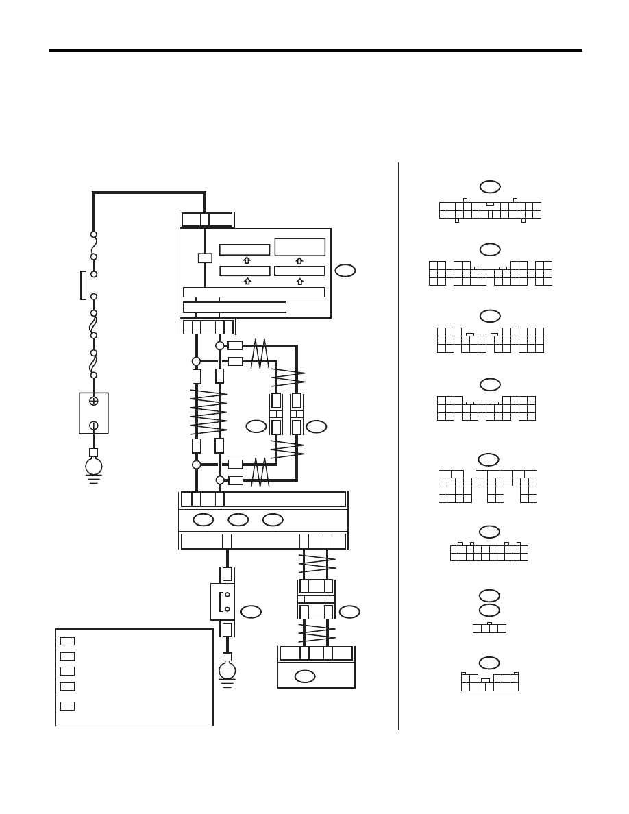
B: CHECK SPORT SHIFT INDICATOR LIGHT
DIAGNOSIS:
Output signal circuit of SPORT shift indicator light is open or shorted.
TROUBLE SYMPTOM:
• SPORT shift indicator light does not illuminate or remains illuminated.
• SPORT shift indicator light display does not change.
WIRING DIAGRAM:
AT-04895
3
21
22
i10
i84
A:
B280
B:
A26
A27
B20
B30
21
20
TCM
B55
i10
i84
B280
2
1
3 4
6 7 8 9 10
22
21
20
19
18
17
16
15
14
13
12
11
5
8
7
6
5
4
3
2
1
22 23
21
20
19
16
15
14
13
12
11
10
9
34 35
33
32
17
30
18
31
29
28
27
26
25
24
8
7
6
5
4
3
2
1
22
23
21
20
19
16
15
14
13
12
11
10
9
17
30
18
29
28
27
26
25
24
A:
B:
B365
i107
i106
1 2 3 4 5 6 7 8 9 10
11 12 13 14 15 16 17 18 19 20
1
*
2
*
1
*
2
*
:
:
1
*
2
*
:
*
1 2 3 4
MAIN SBF
SBF-6
No.
5
E
B365
B55
5
6
7
8
2
1
9
4
3
10
24
22 23
25
11 12 13 14 15
26 27
28
16 17 18 19
20 21
29 30 31
32 33
34 35
:
WN
:
ON
WN
WN
ON
i107
i106
*
*
*
*
ON
WN
WN
ON
ON
C26
B116
8
9
E
B116
1 2
3 4 5
6 7 8 9 10 11 12
LCD DRIVER
LCD (AT /
SPORT SHIFT)
B281
C:
B281
8
7
6
5
4
3
2
1
22 23
21
20
19
16
15
14
13
12
11
10
9
17 18
28
27
26
25
24
C:
WITH NAVIGATION
WITHOUT NAVIGATION
TERMINAL No. OPTIONAL ARRANGEMENT
AMONG 1, 2, 3, 11, 12 AND 13
TERMINAL No. OPTIONAL ARRANGEMENT
TERMINAL No. OPTIONAL ARRANGEMENT
AMONG 8, 9, 10, 18, 19 AND 20
COMBINATION
METER
BODY
INTEGRATED UNIT
IGNITION
SWITCH
B
A
TTER
Y
CAN
JOINT
CONNECTOR
CAN
JOINT
CONNECTOR
CAN TRANSCEIVER & RECEIVER
MICRO COMPUTER
LCD FULL DOT
AT
SELECT
LEVER
DRIVE CIRCUIT
CAN
JOINT
CONNECTOR
5AT(diag)-110
Diagnostic Procedure without Diagnostic Trouble Code (DTC)
AUTOMATIC TRANSMISSION (DIAGNOSTICS)
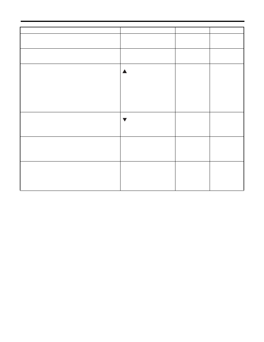
Step
Check
Yes
No
1
CHECK BODY INTEGRATED UNIT.
Check DTC of the body integrated unit.
Is DTC of AT CAN communica-
tion circuit displayed?
Perform the diag-
nosis according to
DTC.
Go to step 2.
2
CHECK TCM.
Check DTC of TCM.
Is DTC of AT CAN communica-
tion circuit displayed?
Perform the diag-
nosis according to
DTC.
Go to step 3.
3
CHECK TCM.
1) Turn the ignition switch to OFF.
2) Connect the Subaru Select Monitor to data
link connector.
3) Turn the ignition switch to ON. (engine OFF)
4) Turn the Subaru Select Monitor switch to
ON.
5) Shift the AT select lever to manual mode
side, and shift down the AT select lever.
6) Read the indicator.
Is the gear position at 1 and
“
” displayed?
Go to step 4.
Replace the TCM.
<Ref. to 5AT-60,
Transmission Con-
trol Module
(TCM).>
4
CHECK TCM.
1) Shift up the AT select lever.
2) Read the indicator.
Is the gear position at 2 and
“
” displayed?
Go to step 5.
Replace the TCM.
<Ref. to 5AT-60,
Transmission Con-
trol Module
(TCM).>
5
CHECK BODY INTEGRATED UNIT.
Read the gear position data using Subaru
Select Monitor.
Is the SPORT shift gear posi-
tion 2?
Go to step 6.
Check the body
integrated unit.
<Ref. to SL-56,
Body Integrated
Unit.>
6
CHECK COMBINATION METER.
Is the SPORT shift indicator
OK?
Refer to “Symp-
tom Related Diag-
nostic”. <Ref. to
5AT(diag)-113,
General Diagnos-
tic Table.>
Replace the com-
bination meter
assembly. <Ref. to
IDI-22, Combina-
tion Meter.>
Нет комментариевНе стесняйтесь поделиться с нами вашим ценным мнением.
Текст