Subaru Legacy IV (2008 year). Service manual — part 896
DS-29
Rear Drive Shaft
DRIVE SHAFT SYSTEM
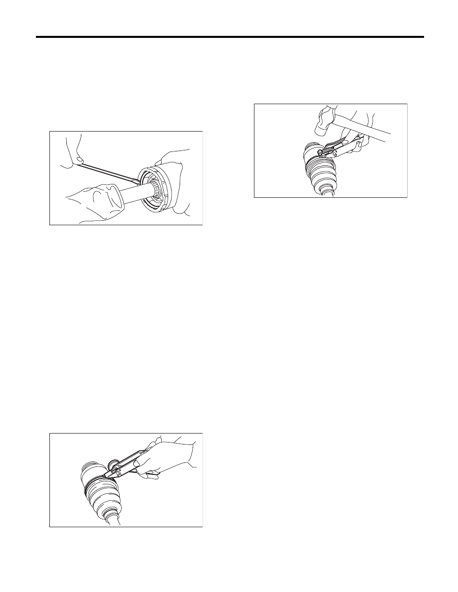
10) Install the snap ring in the groove on the DOJ
outer race.
NOTE:
• Assure that the balls, cage and inner race are
completely fitted in the outer race of DOJ.
• Use care not to place the matched position of
snap ring in the ball groove of outer race.
• Pull the shaft lightly and assure that the snap ring
is completely fitted in the groove.
11) Apply an even coat of the specified grease [20
to 30 g (0.71 to 1.06 oz)] to the entire inner surface
of boot. Also apply grease to the shaft.
12) Install the DOJ boot taking care not to twist it.
NOTE:
• The inside of the large end of DOJ boot and the
boot groove shall be cleaned so as to be free from
grease and other substances.
• When installing the DOJ boot, position the outer
race of DOJ at center of the stroke.
13) Put a new band through the clip and wind twice
in the band groove of the boot.
14) Pinch the end of band with pliers. Hold the clip
and tighten securely.
NOTE:
When tightening boot, use care so that the air with-
in the boot is appropriate.
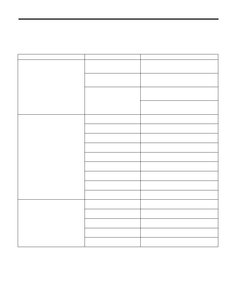
15) Tighten the band using the ST.
ST
925091000
BAND TIGHTENING TOOL
NOTE:
Tighten the band until it cannot be moved by hand.
16) Tap the clip with the punch provided at the end
of the ST.
ST
925091000
BAND TIGHTENING TOOL
NOTE:
Tap to an extent that the boot underneath is not
damaged.
17) Cut off the band with an allowance of about 10
mm (0.39 in) left from the clip and bend this allow-
ance over the clip.
NOTE:
Be careful so that the end of the band is in close
contact with clip.
18) Install the BJ boot or EBJ boot in the same pro-
cedure as a DOJ boot.
19) Extend and retract the DOJ repeatedly to pro-
vide an equal coating of grease.
E: INSPECTION
Check the removed parts for damage, wear, corro-
sion etc. Repair or replace if defective.
• DOJ (Double Offset Joint)
Check for seizure, corrosion, damage, wear and
excessive play.
• EBJ (High-efficiency Compact Ball Fixed Joint)
Check for seizure, corrosion, damage, wear and
excessive play.
• Shaft
Check for excessive bending, twisting, damage
and wear.
• BJ (Bell Joint)
Check for seizure, corrosion, damage and exces-
sive play.
• Boot
Check for wear, warping, breakage and scratches.
• Grease
Check for discoloration and fluidity.
DS-00125
DS-00132
DS-00133
DS-30
General Diagnostic Table
DRIVE SHAFT SYSTEM
8. General Diagnostic Table
A: INSPECTION
NOTE:
Vibration while cruising may be caused by an unbalanced tire, improper tire inflation pressure, improper
wheel alignment, etc.
Symptom
Possible cause
Corrective action
Noise or vibration from propeller shaft
Center bearing
Check the center bearing. <Ref. to DS-12, CEN-
TER BEARING FREE PLAY, INSPECTION, Pro-
peller Shaft.>
Runout of propeller shaft
Check for deflection of the propeller shaft. <Ref.
to DS-12, RUNOUT OF PROPELLER SHAFT,
INSPECTION, Propeller Shaft.>
Loose or gap at connections
Check the joints and connectors. <Ref. to DS-12,
JOINTS AND CONNECTIONS, INSPECTION,
Propeller Shaft.>
Check the spline and bearing. <Ref. to DS-12,
SPLINES AND BEARING, INSPECTION, Pro-
peller Shaft.>
Abnormal wheel vibration
Wheel is out of balance.
Check the wheel balance. <Ref. to WT-8,
ADJUSTMENT, Wheel Balancing.>
Front wheel alignment
Check the front wheel alignment. <Ref. to FS-6,
INSPECTION, Wheel Alignment.>
Rear wheel alignment
Check the rear wheel alignment. <Ref. to RS-7,
INSPECTION, Wheel Alignment.>
Front strut
Check the front strut. <Ref. to FS-23, INSPEC-
TION, Front Strut.>
Rear shock absorber
Check the rear shock absorber. <Ref. to RS-16,
INSPECTION, Rear Shock Absorber.>
Front drive shaft
Check the front drive shaft. <Ref. to DS-25,
INSPECTION, Front Drive Shaft.>
Rear drive shaft
Check the rear drive shaft. <Ref. to DS-29,
INSPECTION, Rear Drive Shaft.>
Front hub unit bearing
Check the front hub unit bearing. <Ref. to DS-18,
INSPECTION, Front Hub Unit Bearing.>
Rear hub unit bearing
Check the rear hub unit bearing. <Ref. to DS-21,
INSPECTION, Rear Hub Unit Bearing.>
Noise from the underbody
Wheel is out of balance.
Check the wheel balance. <Ref. to WT-8,
ADJUSTMENT, Wheel Balancing.>
Front wheel alignment
Check the front wheel alignment. <Ref. to FS-6,
INSPECTION, Wheel Alignment.>
Rear wheel alignment
Check the rear wheel alignment. <Ref. to RS-7,
INSPECTION, Wheel Alignment.>
Front strut
Check the front strut. <Ref. to FS-23, INSPEC-
TION, Front Strut.>
Rear shock absorber
Check the rear shock absorber. <Ref. to RS-16,
INSPECTION, Rear Shock Absorber.>
ABS-2
General Description
ABS
1. General Description
A: SPECIFICATION
Item
Specification or identification
ABS wheel speed sensor
ABS wheel speed sensor gap
(for reference)
Front
0.77 — 1.43 mm (0.030 — 0.056 in)
Rear
0.64 — 1.56 mm (0.025 — 0.061 in)
Identifications of harness
(marks, color)
Front
RH
K1 (White)
LH
K2 (Yellow)
Rear
RH
K5 (White)
LH
K6 (Yellow)
G sensor
G sensor voltage
2.3
r0.2 V
ABSCM&H/U identification
AT (Except for OUTBACK)
JG
MT (Except for OUTBACK)
JH
AT (OUTBACK)
JK
MT (OUTBACK)
JM
ABS-3
General Description
ABS
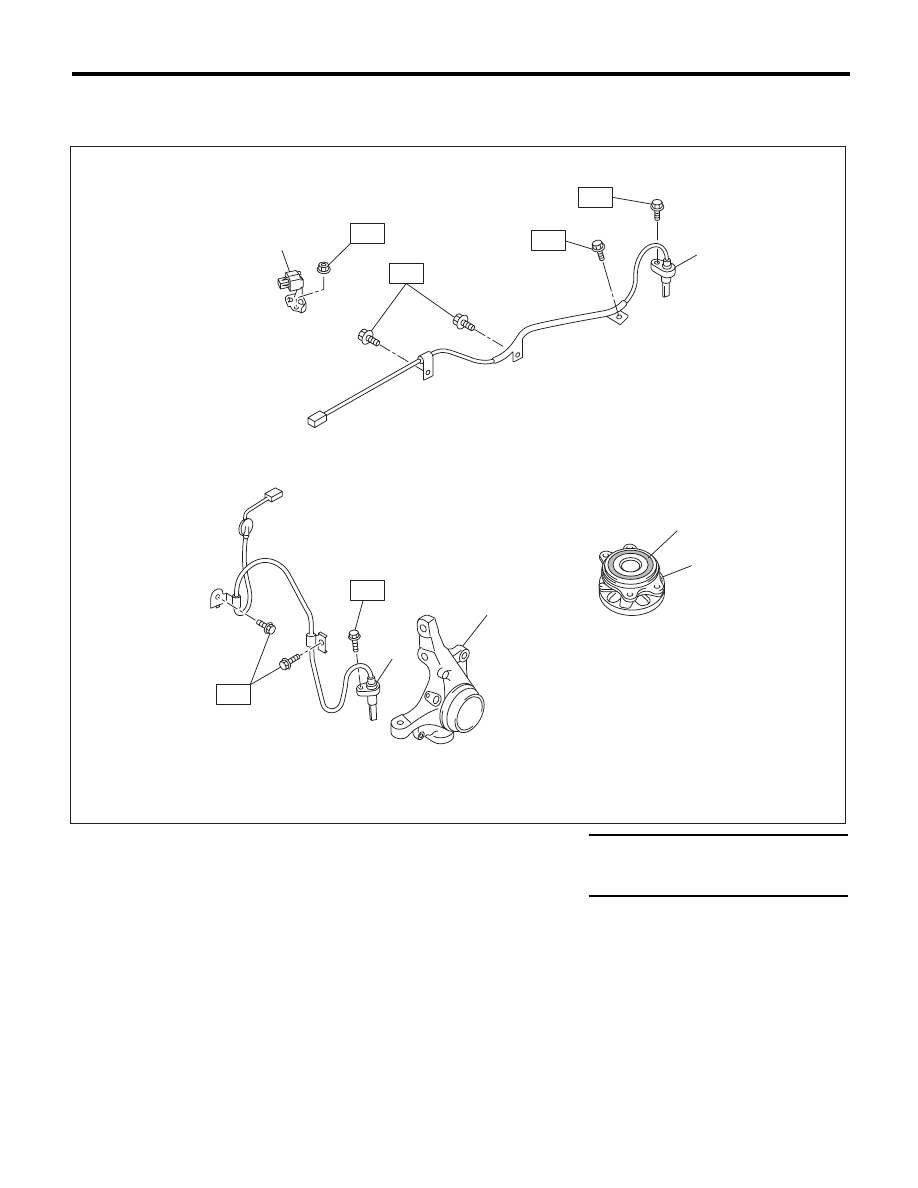
B: COMPONENT
1. ABS WHEEL SPEED SENSOR
(1)
G sensor
(4)
Rear ABS wheel speed sensor LH Tightening torque:N·m (kgf-m, ft-lb)
(2)
Front ABS wheel speed sensor LH
(5)
Hub unit bearing
T1: 7.5 (0.76, 5.5)
(3)
Front housing
(6)
Magnetic encoder
T2: 33 (3.3, 24)
T1
ABS00380
T2
T1
(1)
(5)
(4)
(3)
(2)
T2
T1
(6)
T2
Нет комментариевНе стесняйтесь поделиться с нами вашим ценным мнением.
Текст