Subaru Legacy IV (2008 year). Service manual — part 734
5AT-60
Transmission Control Module (TCM)
AUTOMATIC TRANSMISSION
19.Transmission Control Module
(TCM)
A: REMOVAL
1) Disconnect the ground cable from battery.
2) Remove the lower cover and then disconnect
the connector.
3) Disconnect the connector from TCM.
4) Remove the TCM.
B: INSTALLATION
1) Install the TCM.
Tightening torque:
7.5 N·m (0.8 kgf-m, 5.5 ft-lb)
2) Connect the connector to the TCM.
3) Install in the reverse order of removal.
4) Perform Clear Memory 2 operation. <Ref. to
5AT(diag)-20, CLEAR MEMORY MODE, OPERA-
TION, Subaru Select Monitor.>
5) Execute the learning control promotion. <Ref. to
5AT(diag)-24, PROCEDURE, Learning Control.>
6) Perform the inspection at the end of repair work,
and make sure there is no faulty as below;
• Excessive shift shock
• Oil leakage from the transmission body, etc.
• Occurrence of noise caused by interference etc.
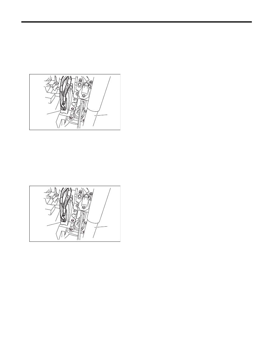
(A) Transmission control module (TCM)
(B) Steering column
(A) Transmission control module (TCM)
(B) Steering column
AT-04384
(A)
(B)
AT-04384
(A)
(B)
5AT-61
Lateral G Sensor
AUTOMATIC TRANSMISSION
20.Lateral G Sensor
A: NOTE
For removal and installation, refer to “Vehicle Dy-
namics Control (VDC)” system. <Ref. to VDC-16,
Yaw Rate and Lateral G Sensor.>
5AT-62
ATF Cooler Pipe and Hose
AUTOMATIC TRANSMISSION
21.ATF Cooler Pipe and Hose
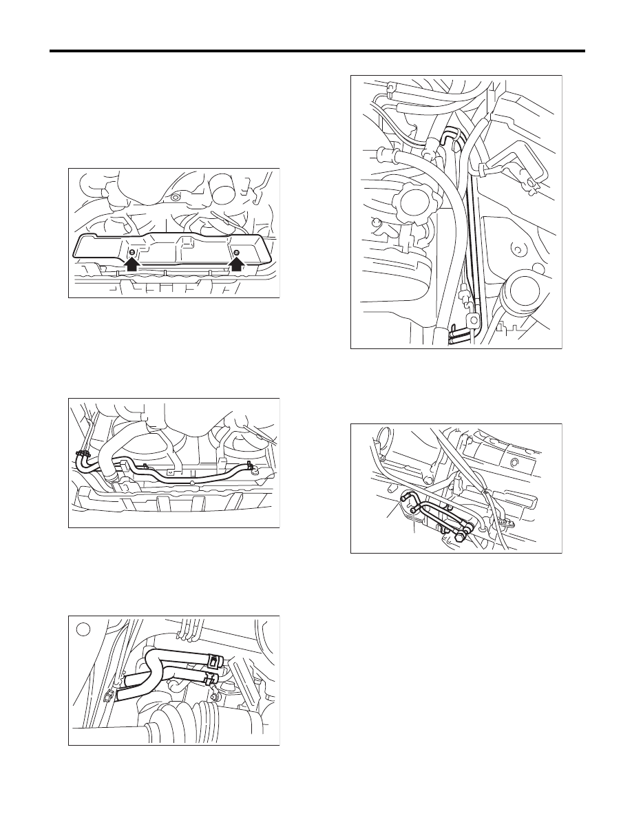
A: REMOVAL
1) Set the vehicle on a lift.
2) Remove the battery.
3) Lift up the vehicle.
4) Remove the under cover.
5) Remove the heat shield cover.
6) Disconnect the ATF cooler hose from the radia-
tor.
NOTE:
• Do not use a screwdriver or other pointed tools.
• If it is hard to remove the hose, wrap the hose
with cloth to prevent from damaging it, and while
turning with pliers, pull straight out by hand.
7) Disconnect the ATF cooler hoses from the pipes.
NOTE:
• Do not use a screwdriver or other pointed tools.
• If it is hard to remove the hose, wrap the hose
with cloth to prevent from damaging it, and while
turning with pliers, pull straight out by hand.
8) Disconnect the ATF cooler pipe from frame.
9) Remove the ATF inlet pipe and outlet pipe.
NOTE:
When disconnecting the outlet pipe, be careful not
to lose the ball and spring used together with re-
taining screw.
CO-02355
AT-01345
AT-04451
(A) ATF outlet pipe
(B) ATF inlet pipe
AT-01347
AT-01383
(A)
(B)
5AT-63
ATF Cooler Pipe and Hose
AUTOMATIC TRANSMISSION
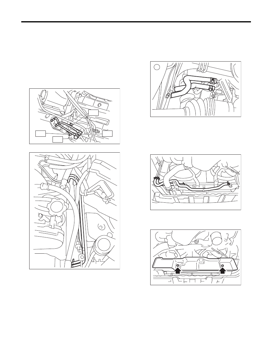
B: INSTALLATION
1) Install the ATF inlet pipe and outlet pipe with new
washers.
NOTE:
Use new bolts for the contact area of the converter
case.
Tightening torque:
T1: 40 N·m (4.1 kgf-m, 29.5 ft-lb)
T2: 38 N·m (3.9 kgf-m, 28.0 ft-lb)
T3: 45 N·m (4.6 kgf-m, 33.2 ft-lb)
2) Install the ATF cooler pipe to frame.
3) Connect the ATF cooler hose to the pipe on the
transmission side.
NOTE:
• Install so that the hose is not folded over, exces-
sively bent or twisted.
• Insert the hose to the specified position.
4) Connect the ATF cooler hose to the pipe on the
radiator side.
NOTE:
• Install so that the hose is not folded over, exces-
sively bent or twisted.
• Insert the hose to the specified position.
5) Install the heat shield cover.
Tightening torque:
3 N·m (0.3 kgf-m, 2.2 ft-lb)
6) Install the under cover.
7) Install the battery.
8) Fill ATF. <Ref. to 5AT-28, Automatic Transmis-
sion Fluid.>
NOTE:
Make sure there are no ATF leaks in joints between
the transmission, radiator, pipes, and hoses.
AT-03133
T2
T1
T2
T3
AT-01347
AT-04451
AT-01345
CO-02355
Нет комментариевНе стесняйтесь поделиться с нами вашим ценным мнением.
Текст