Subaru Legacy IV (2008 year). Service manual — part 902
ABS(diag)-7
General Description
ABS (DIAGNOSTICS)
3. General Description
A: CAUTION
1. SUPPLEMENTAL RESTRAINT SYSTEM
“AIRBAG”
Airbag system wiring harness is routed near the
ABS wheel speed sensor and ABSCM&H/U.
CAUTION:
• All airbag system wiring harness and con-
nectors are colored yellow. Do not use electri-
cal test equipment on these circuits.
• Be careful not to damage the airbag system
wiring harness when servicing the ABS wheel
speed sensor and ABSCM&H/U.
B: INSPECTION
Before performing diagnosis, check the following
item which might affect ABS problems.
1. BATTERY
Measure the battery voltage and check electrolyte.
Standard voltage:
12 V or more
Specific gravity:
1.260 or more
2. GROUND
Check the tightening torque of ground (GB-7) bolt
of ABS.
Tightening torque:
13 N·m (1.3 kgf-m, 9.6 ft-lb)
3. BRAKE FLUID
1) Check the brake fluid level.
2) Check the brake fluid for leaks.
4. HYDRAULIC UNIT
Check the hydraulic unit.
• When using the brake tester <Ref. to ABS-8,
CHECKING THE HYDRAULIC UNIT ABS OPERA-
TION WITH THE BRAKE TESTER, INSPECTION,
ABS Control Module and Hydraulic Control Unit
(ABSCM&H/U).>
• When not using the brake tester <Ref. to ABS-7,
CHECKING THE HYDRAULIC UNIT ABS OPERA-
TION BY PRESSURE GAUGE, INSPECTION,
ABS Control Module and Hydraulic Control Unit
(ABSCM&H/U).>
5. BRAKE DRAG
Check for brake drag.
6. BRAKE PAD AND ROTOR
Check the brake pad and rotor.
• Front <Ref. to BR-13, INSPECTION, Front Brake
Pad.> <Ref. to BR-14, INSPECTION, Front Disc
Rotor.>
• Rear <Ref. to BR-19, INSPECTION, Rear Brake
Pad.> <Ref. to BR-21, INSPECTION, Rear Disc
Rotor.>
7. TIRE
Check the tire specifications, tire wear and air pres-
sure. <Ref. to WT-2, SPECIFICATION, General
Description.>
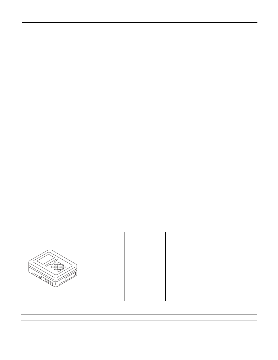
C: PREPARATION TOOL
1. SPECIAL TOOL
2. GENERAL TOOL
ILLUSTRATION
TOOL NUMBER
DESCRIPTION
REMARKS
1B022XU0
SUBARU SELECT
MONITOR III KIT
Used for troubleshooting the electrical system.
TOOL NAME
REMARKS
Circuit tester
Used for measuring resistance, voltage and current.
Oscilloscope
Used for measuring the sensor.
ST1B022XU0
ABS(diag)-8
Electrical Component Location
ABS (DIAGNOSTICS)
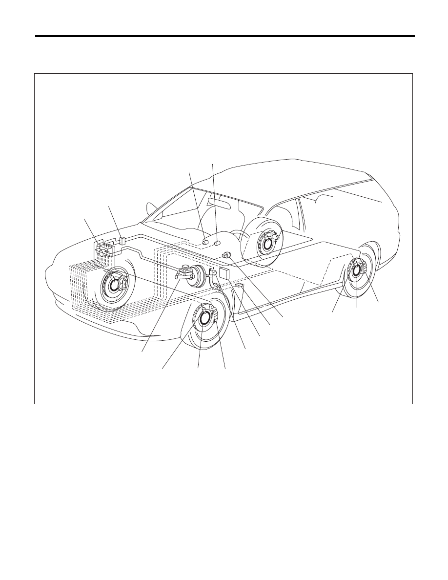
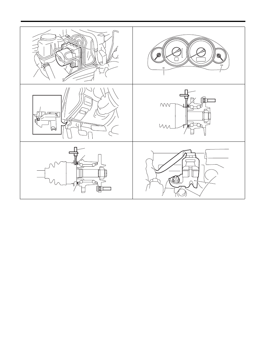
4. Electrical Component Location
A: LOCATION
(1)
ABS control module and hydraulic
control unit (ABSCM&H/U)
(4)
ABS warning light
(9)
G sensor
(5)
Brake and EBD warning light
(10)
Transmission control module
(TCM) (AT model)
(2)
Two-way connector
(6)
Caliper body
(3)
Data link connector
(For Subaru Select Monitor)
(7)
Magnetic encoder seal
(11)
Stop light switch
(8)
ABS wheel speed sensor
(12)
Master cylinder
ABS00591
(1)
(12)
(2)
(10)
(4)
(5)
(11)
(8)
(7)
(6)
(9)
(3)
(8)
(7)
(6)
ABS(diag)-9
Electrical Component Location
ABS (DIAGNOSTICS)
ABS00405
(1)
ABS01068
(4)
(5)
ABS00600
(3)
ABS00408
(8)
(7)
(7)
FRONT
(8)
(7)
(7)
ABS00407
REAR
(9)
ABS00599
ABS(diag)-10
Control Module I/O Signal
ABS (DIAGNOSTICS)
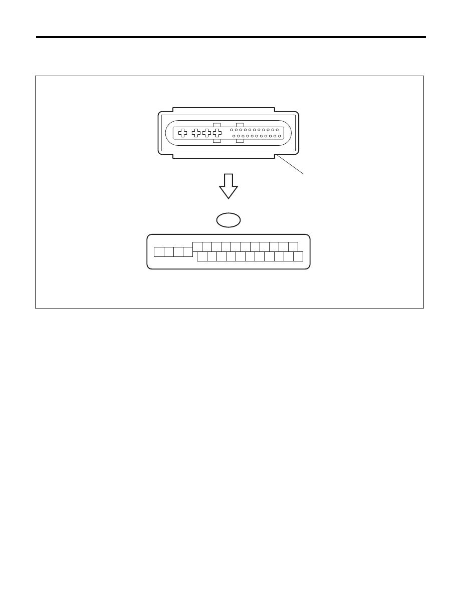
5. Control Module I/O Signal
A: ELECTRICAL SPECIFICATION
NOTE:
• Terminal numbers in ABSCM&H/U connector are shown in the figure.
• ABS warning light illuminates when the connector is removed from ABSCM&H/U.
(1)
ABS control module and hydraulic
control unit (ABSCM&H/U)
connector
ABS00409
B301
7 8 9 10 11
6
5
4
1
15
14
13
12
2 3
22 23 24 25 26
21
20
19
16 17 18
(1)
Нет комментариевНе стесняйтесь поделиться с нами вашим ценным мнением.
Текст