Subaru Legacy IV (2008 year). Service manual — part 903
ABS(diag)-11
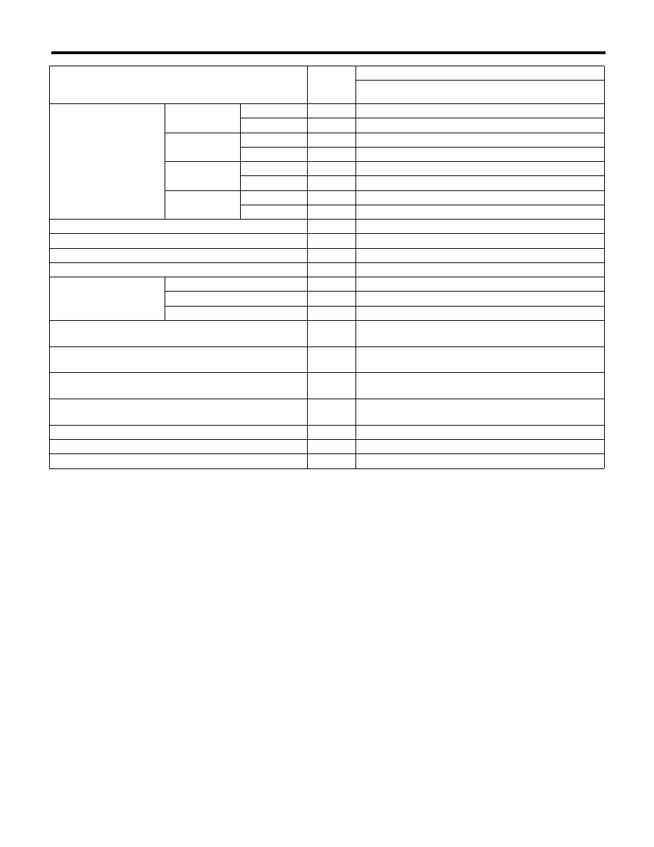
Control Module I/O Signal
ABS (DIAGNOSTICS)
*1: Measure the I/O signal voltage after disconnecting the connector from the ABSCM&H/U terminal.
Description
Terminal
No.
(+) — (–)
Input/Output signal
Measured value and measuring conditions
ABS wheel speed sensor
(Wheel speed sensor)
Front LH wheel
Power supply
16 — 15
4.5 — 16.5 V
Signal
1
5.9 — 16.8 mA: Rectangle waveform
Front RH wheel
Power supply
5 — 15
4.5 — 16.5 V
Signal
6
5.9 — 16.8 mA: Rectangle waveform
Rear LH wheel
Power supply
2 — 15
4.5 — 16.5 V
Signal
17
5.9 — 16.8 mA: Rectangle waveform
Rear RH wheel
Power supply
3 — 15
4.5 — 16.5 V
Signal
4
5.9 — 16.8 mA: Rectangle waveform
CAN communication line (+)
26
2.5 — 1.5 V pulse signal
CAN communication line (–)
11
3.5 — 2.5 V pulse signal
Valve relay power supply *1
14 — 15
10 — 15 V
Motor relay power supply *1
13 — 15
10 — 15 V
G sensor
Power supply
24 — 10
4.75 — 5.25 V
Ground
10
—
Output
21 — 10
2.1 — 2.5 V when the vehicle is on level surface
Stop light switch *1
20 — 15
1.5 V or less when the stop light is OFF; otherwise,
10 — 15 V when the stop light is ON.
ABS warning light
22 — 15
After turning the ignition switch to ON, 10 — 15 V during
1.5 seconds and 1.5 V or less after 1.5 seconds passed.
Brake warning light (EBD warning light)
8 — 15
After turning the ignition switch to ON, 10 — 15 V during
1.5 seconds and 1.5 V or less after 1.5 seconds passed.
Subaru Select Monitor
7 — 15
1.5 V or less when no data is received. 0
mo 12 V pulse
(in communication)
Power supply *1
18 — 15
10 — 15 V when the ignition switch is ON.
Grounding line
15
—
Vehicle speed output signal
23 — 15
0
mo 5 V pulse
ABS(diag)-12
Control Module I/O Signal
ABS (DIAGNOSTICS)
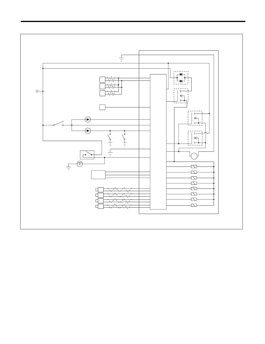
B: WIRING DIAGRAM
(1)
Battery
(11)
Front outlet solenoid valve RH
(21)
Brake warning light
(2)
Ignition switch
(12)
Rear inlet solenoid valve LH
(22)
Parking brake switch
(3)
ABS control module and hydraulic
control unit (ABSCM&H/U)
(13)
Rear outlet solenoid valve LH
(23)
Brake fluid level switch
(14)
Rear inlet solenoid valve RH
(24)
Stop light switch
(4)
ABS control module
(15)
Rear outlet solenoid valve RH
(25)
Stop light
(5)
Valve relay
(16)
Body integrated unit
(26)
G sensor
(6)
Motor relay
(17)
Engine control module (ECM)
(27)
Front ABS wheel speed sensor LH
(7)
Motor
(18)
Transmission control module (TCM)
(28)
Front ABS wheel speed sensor RH
(8)
Front inlet solenoid valve LH
(19)
Data link connector
(29)
Rear ABS wheel speed sensor LH
(9)
Front outlet solenoid valve LH
(20)
ABS warning light
(30)
Rear ABS wheel speed sensor RH
(10)
Front inlet solenoid valve RH
(3)
(7)
(8)
M
(9)
(10)
(19)
(20)
(2)
(4)
(5)
(6)
(1)
(21)
(22)
(24)
(25)
(26)
(27)
(11)
(12)
(13)
(14)
(15)
(28)
(29)
(30)
(23)
(16)
(17)
(18)
ABS01083
ABS(diag)-13
Subaru Select Monitor
ABS (DIAGNOSTICS)
6. Subaru Select Monitor
A: OPERATION
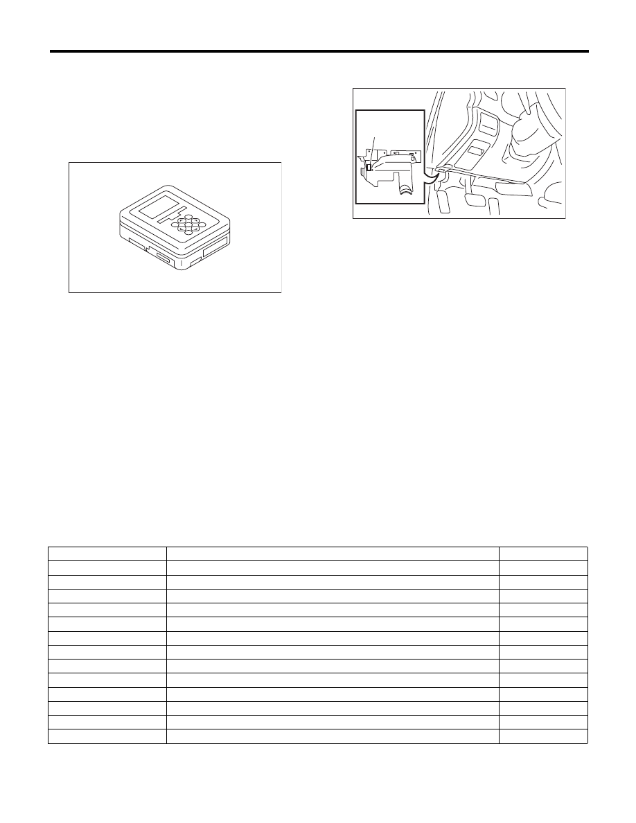
1. HOW TO USE SUBARU SELECT MONITOR
1) Prepare the Subaru Select Monitor kit. <Ref. to
ABS(diag)-7, SPECIAL TOOL, PREPARATION
TOOL, General Description.>
2) Prepare PC with Subaru Select Monitor installed.
3) Connect the USB cable between SDI (Subaru
Diagnosis Interface) and USB port on the personal
computer (dedicated port for the Subaru Select
Monitor).
NOTE:
The dedicated port for the Subaru Select Monitor
means the USB port which was used to install the
Subaru Select Monitor.
4) Connect the diagnosis cable to SDI.
5) Connect SDI to data link connector located in the low-
er portion of the instrument panel (on the driver’s side).
CAUTION:
Do not connect scan tools other than the Suba-
ru Select Monitor.
6) Start the PC.
7) Turn the ignition switch to ON (engine OFF) and
run the “PC application for Subaru Select Monitor”.
NOTE:
For detailed operation procedures, refer to the “PC
application help for Subaru Select Monitor”.
8) If communication is not possible between the
ABS and the Subaru Select Monitor, check the
communication circuit. <Ref. to ABS(diag)-15,
COMMUNICATION FOR INITIALIZING IMPOSSI-
BLE, INSPECTION, Subaru Select Monitor.>
2. READ CURRENT DATA
1) On the «Main Menu» display, select the {Each System Check}.
2) On the «System Selection Menu» display, select the {Brake Control System}.
3) Click the [OK] button after the {ABS} is displayed.
4) On the «Brake Control Diagnosis» display, select the {Current Data Display & Save}.
5) On the «Data Display Menu» display, select the data display method.
6) Using the scroll key, scroll the display screen up or down until necessary data is shown.
• A list of the support data is shown in the following table.
NOTE:
For detailed operation procedures, refer to the “PC application help for Subaru Select Monitor”.
EN-05692
(1) Data link connector
ABS00465
(1)
Display
Contents to be displayed
Unit of measure
FR Wheel Speed
Wheel speed detected by front ABS wheel speed sensor RH is displayed.
km/h or MPH
FL Wheel Speed
Wheel speed detected by front ABS wheel speed sensor LH is displayed.
km/h or MPH
RR Wheel Speed
Wheel speed detected by rear ABS wheel speed sensor RH is displayed.
km/h or MPH
RL Wheel Speed
Wheel speed detected by rear ABS wheel speed sensor LH is displayed.
km/h or MPH
BLS Signal
Brake ON/OFF is displayed.
ON or OFF
G-Sensor
Vehicle acceleration detected by analog G sensor is displayed.
m/s (m/s
2
)
Valve Relay Signal
Valve relay operation signal is displayed.
ON or OFF
ABS Warning Light
ON operation of the ABS warning light is displayed.
ON or OFF
EBD Warning Light
ON operation of the EBD warning light is displayed.
ON or OFF
M. Relay monitor Voltage
Motor relay monitor voltage is displayed.
V
ABS_CM Power Voltage
Voltage supplied to ABSCM&H/U is displayed.
V
ABS Control Flag
ABS control condition is displayed.
ON or OFF
ABS OK B Signal
ABS system normal/abnormal is displayed.
OK or NG
ABS(diag)-14
Subaru Select Monitor
ABS (DIAGNOSTICS)
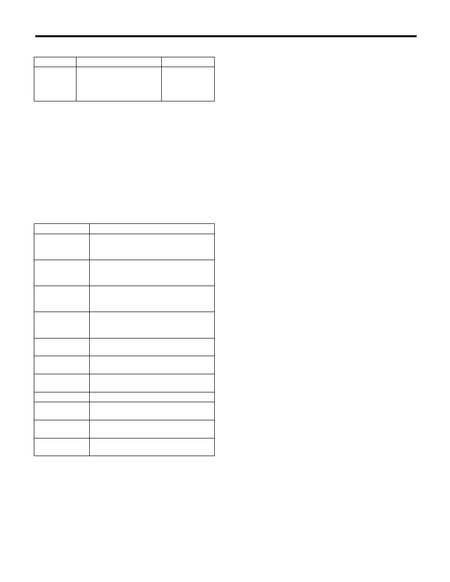
3. ABS SEQUENCE CONTROL
4. FREEZE FRAME DATA
NOTE:
• Data stored at the time of trouble occurrence is
shown on display.
• Each time a trouble occurs, the latest information
is stored in the freeze frame data in memory.
• Up to 3 freeze frame data will be stored.
• If freeze frame data is not stored in memory
properly (due to a drop in ABS control module pow-
er supply etc.), a DTC suffixed with a question mark
“?” is displayed on Subaru Select Monitor display
screen. This shows it may be an unreliable reading.
Display
Contents to be displayed
Index No.
ABS
Sequence
Control
Mode
Operate the valve and
pump motor continuously
to perform the ABS
sequence control.
<Ref. to ABS-
10, ABS
Sequence Con-
trol.>
Display
Contents to be displayed
FR Wheel
Speed
Wheel speed detected by front ABS
wheel speed sensor RH is displayed in
km/h or MPH.
FL Wheel Speed
Wheel speed detected by front ABS
wheel speed sensor LH is displayed in
km/h or MPH.
RR Wheel
Speed
Wheel speed detected by rear ABS
wheel speed sensor RH is displayed in
km/h or MPH.
RL Wheel
Speed
Wheel speed detected by rear ABS
wheel speed sensor LH is displayed in
km/h or MPH.
ABS_CM Power
Voltage
Voltage (V) supplied to ABSCM&H/U is
displayed.
G-Sensor
Vehicle acceleration detected by analog
G sensor is displayed.
M. Relay monitor
Voltage
Motor relay condition is displayed.
BLS Signal
Brake ON/OFF is displayed.
Vehicle Speed
Vehicle speed calculated by ABS control
module is displayed.
ABS Control
Flag
ABS control condition is displayed.
Power Supply
Failure
Whether abnormal voltage occurred or
not is displayed during malfunction.
Нет комментариевНе стесняйтесь поделиться с нами вашим ценным мнением.
Текст