Subaru Legacy IV (2008 year). Service manual — part 984
AC-39
Evaporator
HVAC SYSTEM (HEATER, VENTILATOR AND A/C)
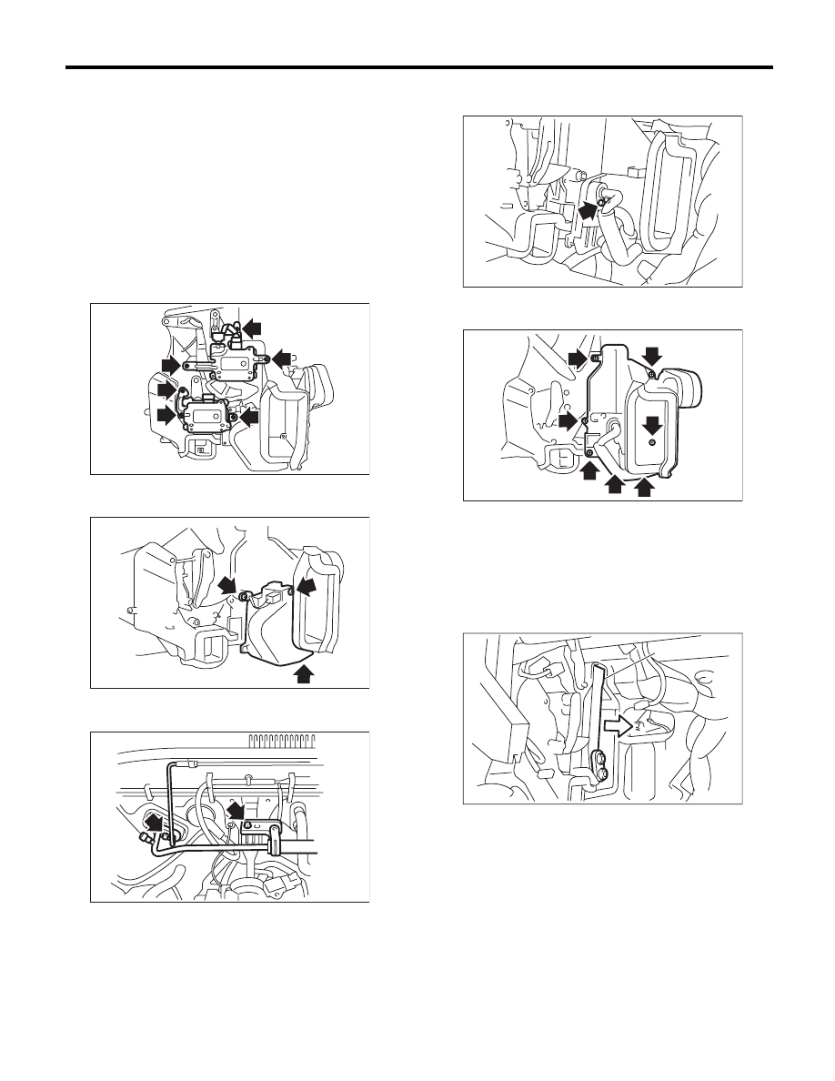
18.Evaporator
A: REMOVAL
1) Using the refrigerant recovery system, drain the
refrigerant. <Ref. to AC-22, PROCEDURE, Refrig-
erant Recovery Procedure.>
2) Disconnect the ground cable from the battery.
3) Remove the blower motor unit assembly. <Ref.
to AC-28, REMOVAL, Blower Motor Unit Assem-
bly.>
4) Disconnect the connector, remove the screw
and then remove the air-mix door actuator and
mode door actuator.
5) Disconnect the connector, remove the pipe cov-
er and evaporator sensor.
6) Remove the bolts securing expansion valve and
pipe in engine compartment.
7) Remove the bolt which holds the pipe to the
evaporator.
8) Remove the screws and clip to remove the evap-
orator cover.
9) Pull out the evaporator (A) in the direction of the
arrow.
CAUTION:
If the evaporator is replaced, add an appropri-
ate amount of compressor oil to evaporator.
<Ref. to AC-27, REPLACEMENT, Compressor
Oil.>
B: INSTALLATION
Install in the reverse order of removal.
AC-00923
AC-00924
AC-00925
AC-00926
AC-01187
AC-00928
(A)
AC-40
Hose and Pipe
HVAC SYSTEM (HEATER, VENTILATOR AND A/C)
19.Hose and Pipe
A: REMOVAL
CAUTION:
• When disconnecting hoses and pipes, do not
apply excessive force. After installing, check
that no torsion or excessive tension applied to
the hoses.
• Seal the disconnected hose with a plug or vi-
nyl tape to prevent foreign matter from enter-
ing.
1) Disconnect the ground cable from the battery.
2) Using the refrigerant recovery system, drain the
refrigerant. <Ref. to AC-22, PROCEDURE, Refrig-
erant Recovery Procedure.>
3) Remove the bolt and detach the hoses and
pipes.
B: INSTALLATION
CAUTION:
• Always replace with new O-rings.
• When connecting hoses and pipes, do not
apply excessive force. After installing, check
that no torsion or excessive tension applied to
the hoses.
1) Install in the reverse order of removal.
2) Charge refrigerant. <Ref. to AC-23, PROCE-
DURE, Refrigerant Charging Procedure.>
Tightening torque:
Refer to “COMPONENT” of “General Descrip-
tion”. <Ref. to AC-11, AIR CONDITIONING
UNIT, COMPONENT, General Description.>
C: INSPECTION
Check the hoses for cracks, damage and expan-
sion. If any fault is found, replace with new parts.
AC-41
Relay and Fuse
HVAC SYSTEM (HEATER, VENTILATOR AND A/C)
20.Relay and Fuse
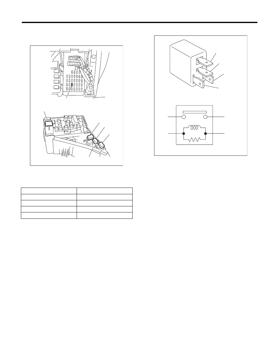
A: LOCATION
B: INSPECTION
While applying battery voltage to the terminal be-
tween (3) and (4), check continuity between (1) and
(2).
If no continuity exists, replace the relay with a new
part.
(1) Joint box
(2) Main fuse box
Main fan relay 1
(A)
Main fan relay 2
(B)
Sub fan relay
(C)
A/C relay
(D)
A/C Fuse
(E)
(E)
(1)
(2)
(A)
(D)
(C)
(B)
AC-01570
(3) — (4): Continuity exists
(1) — (2): Continuity does not exist
AC-00641
(1)
(1)
(2)
(2)
(3)
(3)
(4)
(4)
AC-42
Pressure Switch (Triple Pressure Switch)
HVAC SYSTEM (HEATER, VENTILATOR AND A/C)
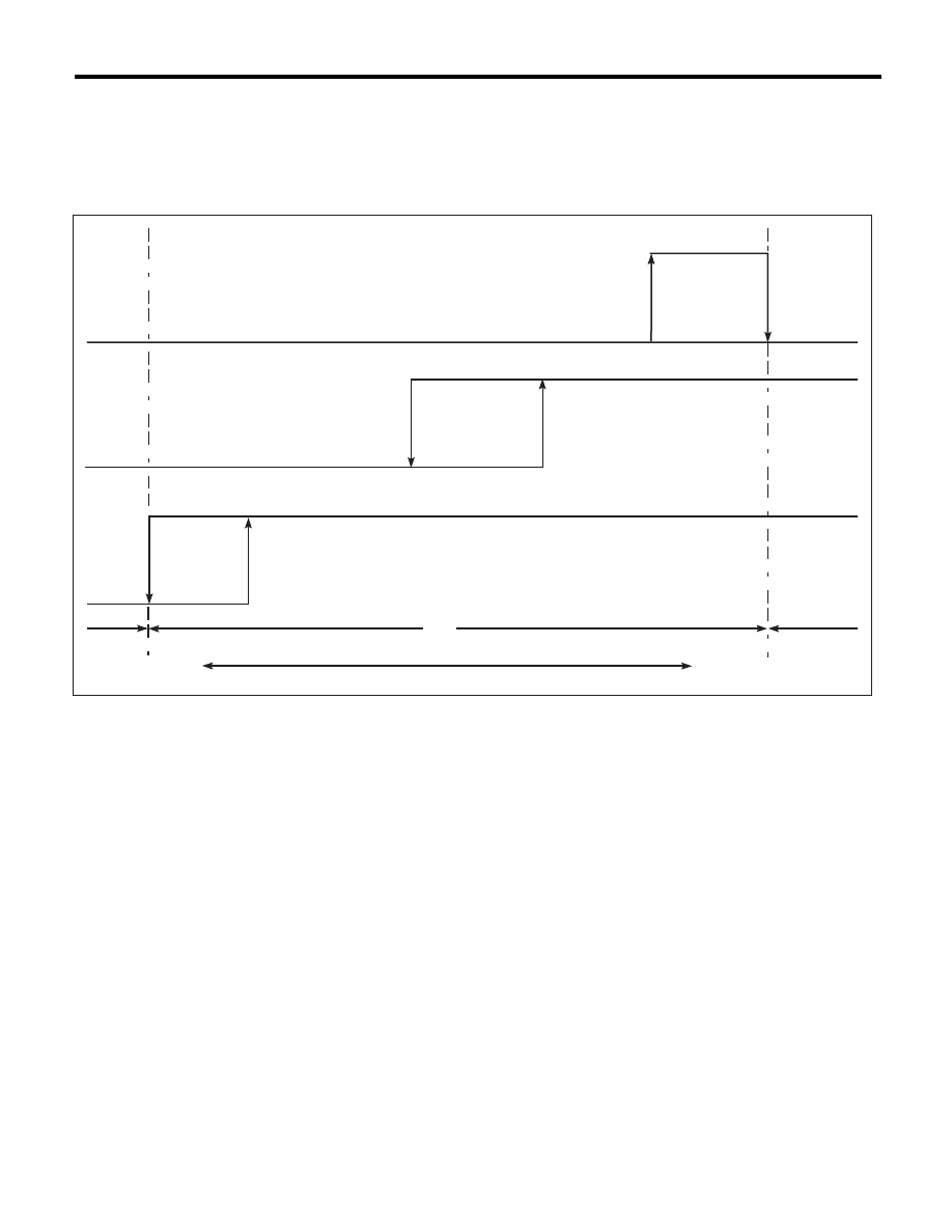
21.Pressure Switch (Triple Pressure Switch)
A: INSPECTION
1) Connect the manifold gauge to the service valve on the high-pressure side.
2) Start the air conditioner, and check the operating pressure of switch by turning the compressor (magnet
clutch) to ON/OFF. Operation of each switch is as follows.
NOTE:
• High pressure switch turns the compressor (magnet clutch) to OFF when the refrigerant pressure be-
comes extremely high to prevent the evaporator, air conditioner piping and expansion valve from getting
damaged or frozen.
• Middle pressure switch effectively controls the radiator fan output by judging height load/low load in normal
range.
• If the refrigerant pressure is abnormally low, the low pressure switch determines that there is insufficient
refrigerant, and turns the compressor (magnetic clutch) OFF since there is a possibility that the compressor
will seize if it is continued to run.
(1)
High pressure switch
(6)
1770
r80 kPa (18.05r0.82 kg/cm
2
,
256.81
r11.6 psi)
(9)
196
r20 kPa (2.0r0.2 kg/cm
2
,
28.4
r2.9 psi)
(2)
Middle pressure switch
(3)
Low pressure switch
(7)
1370
r120 kPa
(13.97
r1.22 kg/cm
2
,
198.65
r14.5 psi)
(10)
ON
(4)
2550
r200 kPa (24r2 kg/cm
2
,
341
r28 psi)
(11)
OFF
(12)
Operative range of compressor
(5)
3140
+50
–200
kPa
(32.02
+0.51
–2.04
kg/cm
2
,
455.4
+72.5
–29.0
psi)
(8)
225
+25
–29
kPa
(2.99
+0.25
–0.3
kg/cm
2
,
3.6
+32.6
–4.2
psi)
(13)
Inoperative range of compressor
(14)
Low pressure
(15)
High pressure
AC-01433
(1)
(9)
(2)
(3)
(8)
(4)
(5)
(6)
(7)
(11)
(10)
(10)
(11)
(11)
(10)
(12)
(13)
(13)
(14)
(15)
Нет комментариевНе стесняйтесь поделиться с нами вашим ценным мнением.
Текст