Subaru Legacy IV (2008 year). Service manual — part 1117
SL-41
Rear Door Lock Actuator
SECURITY AND LOCKS
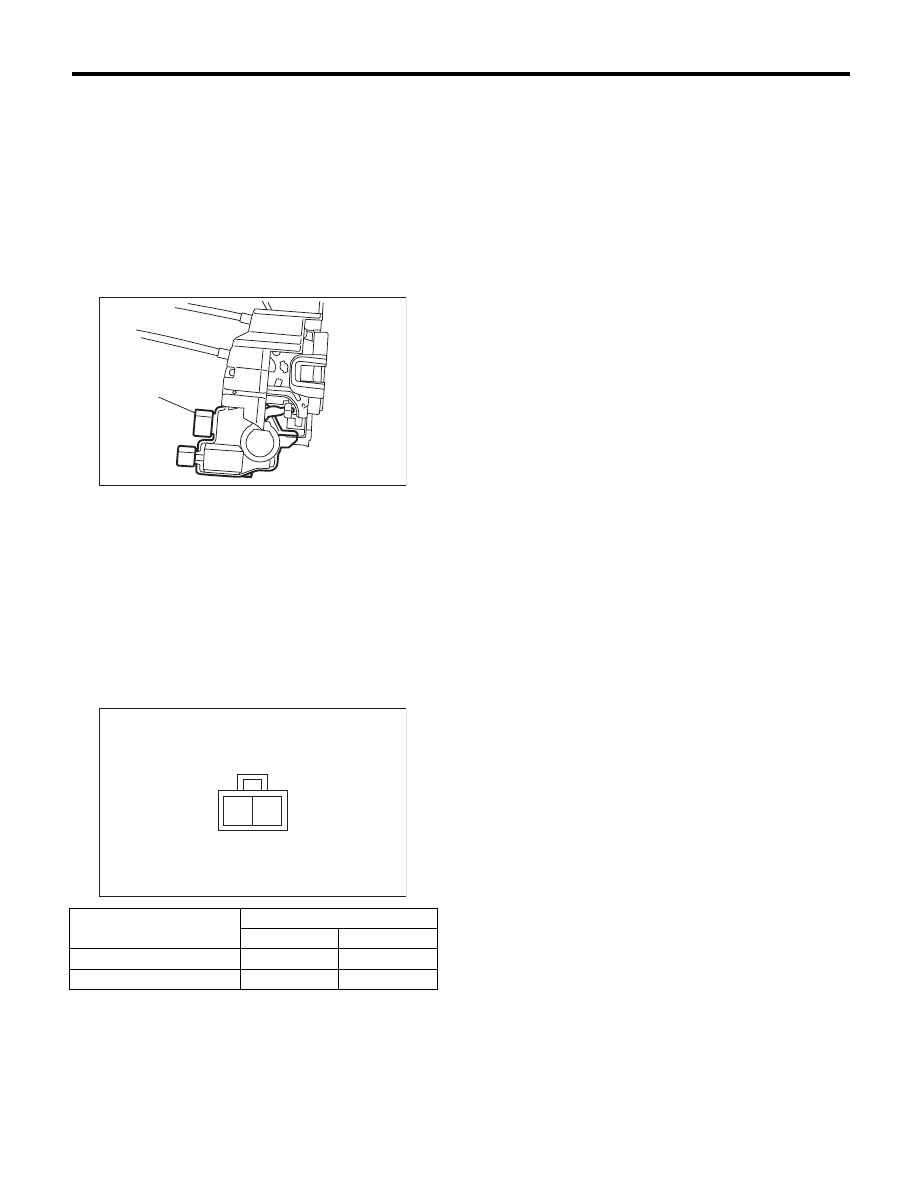
12.Rear Door Lock Actuator
A: REMOVAL
1) Remove the rear door latch and door lock actu-
ator assembly. <Ref. to SL-40, REMOVAL, Rear
Door Latch and Door Lock Actuator Assembly.>
2) Remove the claw of rear door latch security cov-
er, and then remove the cover.
3) Remove the screw from the rear door latch and
door lock actuator, and then remove the door lock
actuator.
B: INSTALLATION
Install in the reverse order of removal.
C: INSPECTION
1) Disconnect the door lock actuator harness con-
nector.
2) Connect the battery to rear door lock actuator
terminals.
If defective, replace the rear door lock actuator.
(1) Rear door lock actuator
Actuator operation
Terminals
No. 1
No. 2
Lock
o Unlock
+
–
Unlock
o Lock
–
+
SL-00234
(1)
SL-00235
2 1
SL-42
Rear Gate Outer Handle
SECURITY AND LOCKS
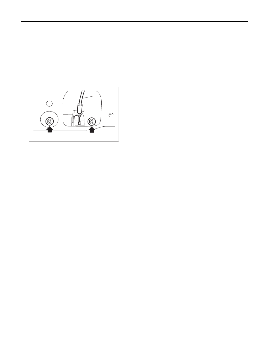
13.Rear Gate Outer Handle
A: REMOVAL
1) Disconnect the ground cable from battery.
2) Remove the rear gate trim. <Ref. to EI-68, RE-
MOVAL, Rear Gate Trim.>
3) Remove the rear gate garnish. <Ref. to EI-75,
REMOVAL, Rear Gate Garnish.>
4) Remove the two nuts, and take out the rear gate
outer handle.
5) Remove cable (1) of the rear gate handle.
B: INSTALLATION
Install in the reverse order of removal.
Tightening torque:
Refer to “COMPONENT” of “General Descrip-
tion”. <Ref. to SL-3, TRUNK LID AND REAR
GATE LOCK, COMPONENT, General Descrip-
tion.>
C: INSPECTION
1) Check the cable of the rear gate handle for de-
formation.
2) Check the rear gate outer handle and cable of
the rear gate handle for smooth operation.
SL-00239
(1)
SL-43
Rear Gate Latch Assembly
SECURITY AND LOCKS
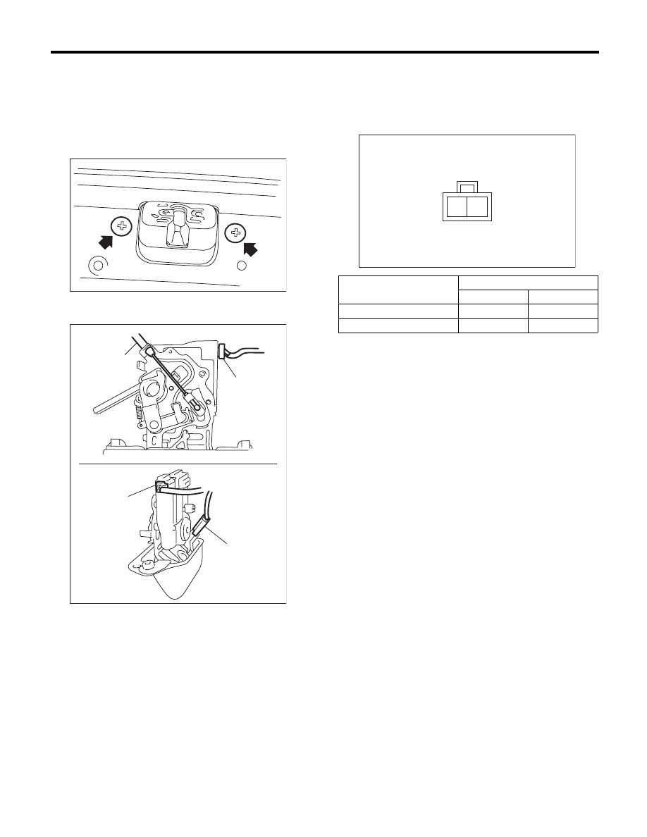
14.Rear Gate Latch Assembly
A: REMOVAL
1) Disconnect the ground cable from battery.
2) Remove the rear gate trim. <Ref. to EI-68, RE-
MOVAL, Rear Gate Trim.>
3) Remove the two screws.
4) Disconnect connectors and cables of the rear
gate handle.
5) Remove the rear gate latch assembly.
B: INSTALLATION
Install in the reverse order of removal.
Tightening torque:
Refer to “COMPONENT” of “General Descrip-
tion”. <Ref. to SL-3, TRUNK LID AND REAR
GATE LOCK, COMPONENT, General Descrip-
tion.>
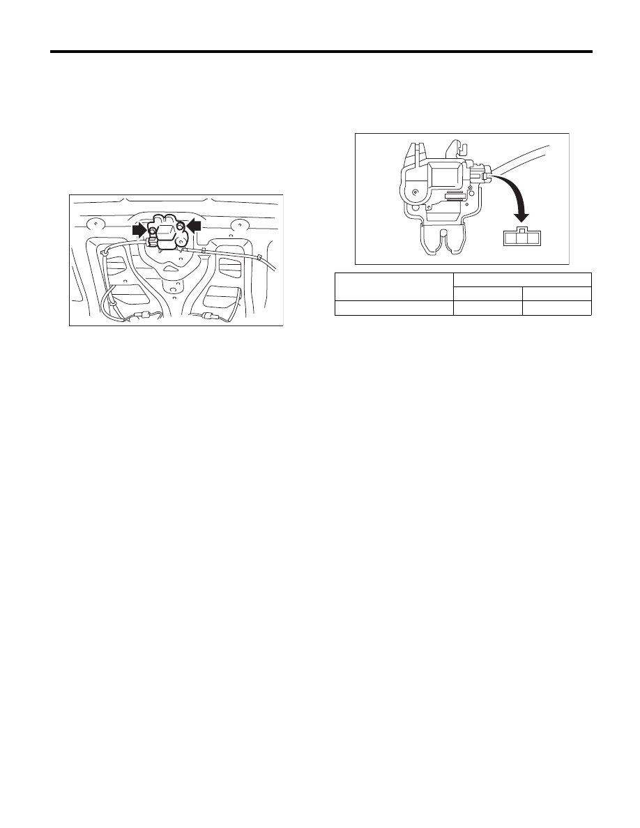
C: INSPECTION
1) Disconnect the rear gate lock actuator harness
connector.
2) Connect the battery to rear gate lock actuator
terminals.
Replace the rear gate latch assembly if faulty.
3) Check the cable of the rear gate handle for de-
formation.
4) Check the lever and cable of the rear gate han-
dle for smooth operation.
(1) Cable
(2) Rear gate lock actuator connector
(3) Rear gate latch switch connector
SL-00240
SL-00301
(2)
(1)
(3)
(2)
Actuator operation
Terminals
No. 1
No. 2
Lock
o Unlock
+
–
Unlock
o Lock
–
+
SL-00235
2 1
SL-44
Trunk Lid Lock Assembly
SECURITY AND LOCKS
15.Trunk Lid Lock Assembly
A: REMOVAL
1) Disconnect the ground cable from battery.
2) Remove the trunk lid release handle. <Ref. to
SL-45, REMOVAL, Trunk Lid Release Handle.>
3) Disconnect the connectors and remove the ca-
ble of the trunk opener.
4) Remove the two bolts to remove the trunk lid
lock assembly.
B: INSTALLATION
Install in the reverse order of removal.
Tightening torque:
Refer to “COMPONENT” of “General Descrip-
tion”. <Ref. to SL-3, TRUNK LID AND REAR
GATE LOCK, COMPONENT, General Descrip-
tion.>
NOTE:
Apply grease to the movable part.
C: INSPECTION
1) Disconnect the trunk lid lock actuator harness
connector.
2) Connect the battery to the trunk lid lock actuator
terminals.
Replace the trunk lid lock assembly if defective.
3) Check the striker for deformation or abnormal
wear.
4) Check the safety lever for improper movement.
5) Check other levers and springs for rust formation
or unsmooth movement.
6) Check the cable of the trunk opener for smooth
operation.
SL-00243
Actuator operation
Terminals
No. 1
No. 2
Lock
o Unlock
–
+
SL-00255
3 2 1
Нет комментариевНе стесняйтесь поделиться с нами вашим ценным мнением.
Текст