Subaru Legacy IV (2008 year). Service manual — part 674
4AT-44
Extension Case Oil Seal
AUTOMATIC TRANSMISSION
11.Extension Case Oil Seal
A: INSPECTION
Confirm that there is no ATF leakage from the joint
of the transmission and propeller shaft. If a leak is
found, replace the oil seal and inspect the propeller
shaft. <Ref. to 4AT-44, REPLACEMENT, Exten-
sion Case Oil Seal.>
B: REPLACEMENT
1) Lift up the vehicle.
2) Clean the transmission exterior.
3) Remove the drain plug (ATF) and completely
drain the ATF.
CAUTION:
Directly after the vehicle has been running or
the engine has been long idle running, the ATF
is hot. Be careful not to burn yourself.
4) Perform replacement with a new gasket, and
tighten the drain plug (ATF).
Tightening torque:
25 N·m (2.5 kgf-m, 18.4 ft-lb)
5) Remove the rear exhaust pipe and muffler.
<Ref. to EX(H4SO)-8, REMOVAL, Rear Exhaust
Pipe.> <Ref. to EX(H4SO)-10, REMOVAL, Muf-
fler.>
6) Remove the heat shield cover.
7) Remove the propeller shaft. <Ref. to DS-10, RE-
MOVAL, Propeller Shaft.>
8) Using the ST, remove the oil seal.
ST
398527700
PULLER ASSY
9) Using the ST, install the oil seal.
ST
498057300
INSTALLER
10) Install the propeller shaft. <Ref. to DS-11, IN-
STALLATION, Propeller Shaft.>
11) Install the heat shield cover.
12) Install the rear exhaust pipe and muffler. <Ref.
to EX(H4SO)-8, INSTALLATION, Rear Exhaust
Pipe.> <Ref. to EX(H4SO)-10, INSTALLATION,
Muffler.>
13) Fill with ATF. <Ref. to 4AT-26, Automatic
Transmission Fluid.>
14) Bleed the air of control valve. <Ref. to 4AT-59,
Air Bleeding of Control Valve.>
15) Check the level and leaks of the ATF. <Ref. to
4AT-26, INSPECTION, Automatic Transmission
Fluid.>
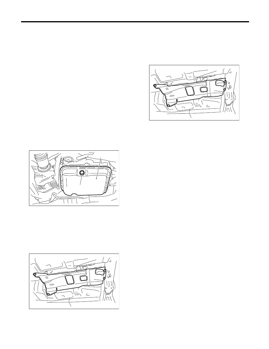
(A) Oil pan
(B) Drain plug (ATF)
AT-04829
(B)
(A)
AT-01331
AT-01331
4AT-45
Differential Side Retainer Oil Seal
AUTOMATIC TRANSMISSION
12.Differential Side Retainer Oil
Seal
A: INSPECTION
Check for leakage of gear oil from differential side
retainer oil seal part. If there is an oil leak, replace
the oil seal and inspect the drive shaft.
B: REPLACEMENT
1) Lift up the vehicle.
2) Remove the front exhaust pipe and center ex-
haust pipe. <Ref. to EX(H4SO)-4, REMOVAL,
Front Exhaust Pipe.> <Ref. to EX(H4SO)-7, RE-
MOVAL, Center Exhaust Pipe.>
3) Remove the differential gear oil drain plug using
TORX
®
bit T70, and then drain differential gear oil.
CAUTION:
• Immediately after the vehicle has been run-
ning or after idling for a long time, the differen-
tial gear oil will be hot. Be careful not to burn
yourself.
• Be careful not to spill the differential gear oil
on exhaust pipe to prevent it from emitting
smoke or causing fires. If differential gear oil is
spilled on the exhaust pipe, wipe it off com-
pletely.
4) Perform replacement with a new gasket, and
tighten the differential gear oil drain plug.
Tightening torque:
Aluminum gasket
44 N·m (4.5 kgf-m, 32.5 ft-lb)
Copper gasket
70 N·m (7.1 kgf-m, 51.6 ft-lb)
5) Separate the front drive shaft from the transmis-
sion. <Ref. to DS-22, REMOVAL, Front Drive
Shaft.>
6) Remove the differential side retainer oil seal us-
ing driver wrapped with vinyl tape etc.
7) Using the ST, install the differential side retainer
oil seal by lightly tapping with a hammer.
ST
18675AA000
DIFFERENTIAL SIDE OIL
SEAL INSTALLER
8) Apply gear oil to the oil seal lips.
9) Using the ST, install the front drive shaft. <Ref.
to DS-22, INSTALLATION, Front Drive Shaft.>
ST
28399SA010
OIL SEAL PROTECTOR
10) Install the front exhaust pipe and the center ex-
haust pipe. <Ref. to EX(H4SO)-5, INSTALLATION,
Front Exhaust Pipe.> <Ref. to EX(H4SO)-7, IN-
STALLATION, Center Exhaust Pipe.>
11) Lower the vehicle.
12) Fill with differential gear oil through the oil level
gauge hole. <Ref. to 4AT-28, Differential Gear Oil.>
13) Check the level of differential gear oil. <Ref. to
4AT-28, INSPECTION, Differential Gear Oil.>
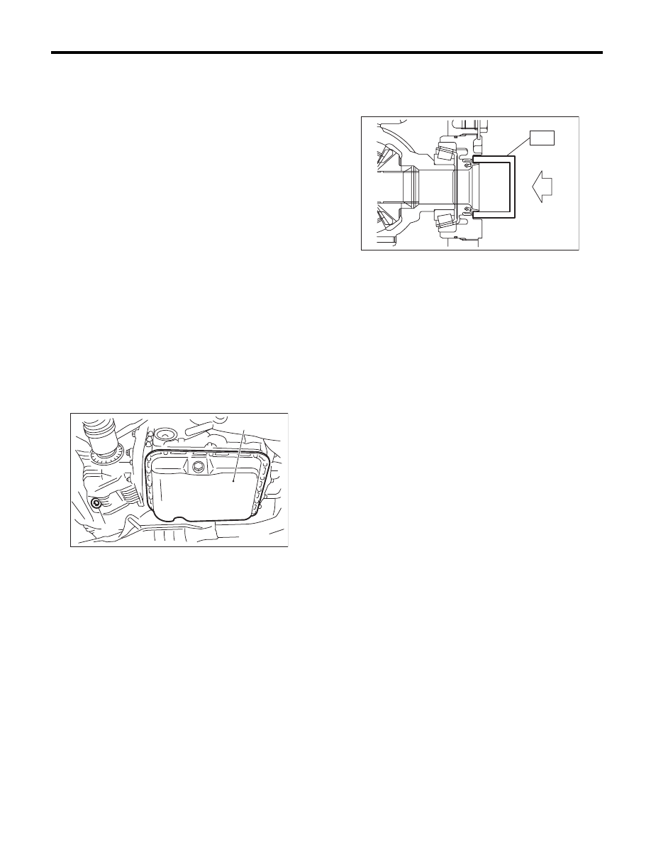
(A) Oil pan
(B) Differential gear oil drain plug
AT-04830
(A)
(B)
AT-00029
ST
4AT-46
Inhibitor Switch
AUTOMATIC TRANSMISSION
13.Inhibitor Switch
A: INSPECTION
When the driving condition or starter motor opera-
tion is improper, first check the shift linkage for im-
proper operation. If the shift linkage is functioning
properly, check the inhibitor switch.
1) Disconnect the inhibitor switch connector.
2) Check continuity in inhibitor switch circuits with
the select lever moved to each position.
NOTE:
• Also check that there is no continuity in the igni-
tion circuit when the select lever is in the “R” and
“D” ranges.
• If the inhibitor switch does not operate, check for
poor contact of the connector on transmission side.
3) Check that there is continuity at equal points
when the select lever is turned 1.5° in both direc-
tions from the “N” range.
If there is continuity in only one direction or in other
points, adjust the inhibitor switch. <Ref. to 4AT-46,
ADJUSTMENT, Inhibitor Switch.>
4) Repeat the above inspection in other gear rang-
es. If there are faults, adjust the select cable. <Ref.
to CS-32, ADJUSTMENT, Select Cable.>
B: ADJUSTMENT
1) Set the select lever to “N” range.
2) Loosen the two bolts holding the inhibitor switch.
3) Insert the ST as vertical as possible into the
holes of the shifter arm and switch body.
ST
499267300
STOPPER PIN
4) Tighten the two bolts holding the inhibitor switch.
Tightening torque:
5 N·m (0.5 kgf-m, 3.7 ft-lb)
5) Repeat the inspection of the inhibitor switch. If
the inhibitor switch is determined to be “faulty”, re-
place it.
Signal sent to TCM
Range
Pin No.
P
4 — 3
R
4 — 2
N
4 — 1
D
4 — 8
Ignition circuit
P/N
12 — 11
Back-up light circuit
R
10 — 9
(A) Inhibitor switch connector
AT-00030
( 4 ) ( 3 ) ( 2 ) ( 1 )
( 5 )
( 6 )
( 7 )
( 8 )
( 9 )
(10)
(11)
(12)
(A)
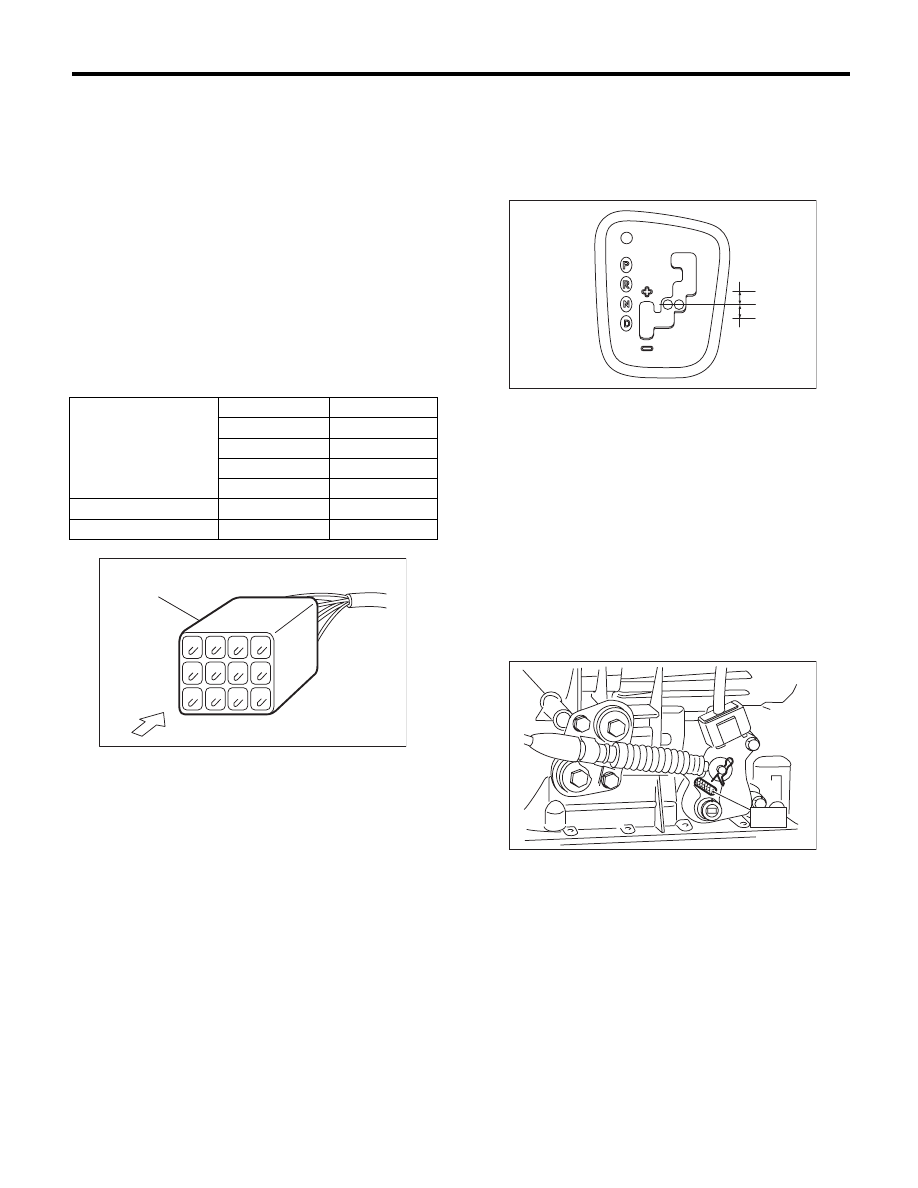
(A) Continuity does not exist.
(B) Continuity exists.
(C) 1.5°
AT-02206
(A)
(A)
(C)
(B)
AT-04866
S T
4AT-47
Inhibitor Switch
AUTOMATIC TRANSMISSION
C: REMOVAL
1) Set the vehicle on a lift.
2) Set the select lever to “N” range.
3) Lift up the vehicle.
4) Remove the front and center exhaust pipes.
<Ref. to EX(H4SO)-4, REMOVAL, Front Exhaust
Pipe.>
5) Remove the snap pin and washer from the
shifter arm.
6) Remove the plate assembly from the transmis-
sion case.
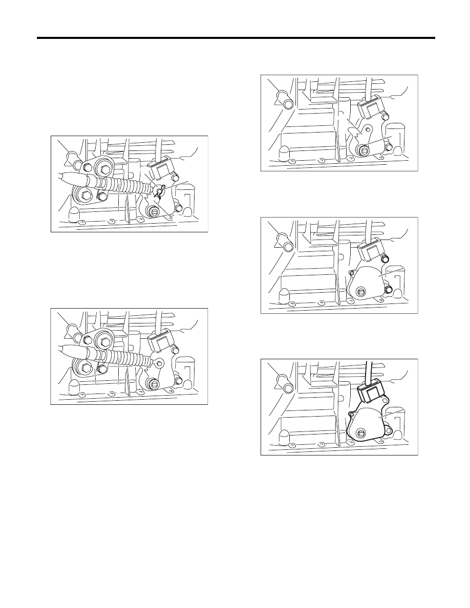
7) Remove the spring pin and remove the shifter
arm.
ST
398791600
REMOVER
8) Remove the two inhibitor switch securing bolts.
9) Remove the inhibitor switch from the transmis-
sion.
10) Disconnect the inhibitor switch harness con-
nector from the inhibitor switch.
(A) Shifter arm
(B) Snap pin
(C) Select cable
(D) Washer
(A) Select cable
(B) Plate ASSY
AT-04867
(C)
(A)
(B)
(D)
CS-00955
(A)
(B)
(A) Spring pin
(B) Shifter arm
(A) Inhibitor switch
(A) Inhibitor switch
AT-04868
(B)
(A)
AT-04785
(A)
AT-04786
(A)
Нет комментариевНе стесняйтесь поделиться с нами вашим ценным мнением.
Текст