Subaru Legacy IV (2008 year). Service manual — part 747

5AT(diag)-3
Basic Diagnostic Procedure
AUTOMATIC TRANSMISSION (DIAGNOSTICS)
6
PERFORM DIAGNOSIS.
1) Inspect using “Diagnostic Procedure with
Diagnostic Trouble Code (DTC)”. <Ref. to
5AT(diag)-35, Diagnostic Procedure with Diag-
nostic Trouble Code (DTC).>
NOTE:
For DTC table, refer to “List of Diagnostic Trou-
ble Code (DTC)”. <Ref. to 5AT(diag)-32, List of
Diagnostic Trouble Code (DTC).>
2) Repair the trouble cause.
3) Perform the Clear Memory Mode.
4) Perform the Inspection Mode. <Ref. to
5AT(diag)-22, Inspection Mode.>
5) Display DTC.
Is DTC displayed?
Inspect using
“Diagnostic Proce-
dure with Diagnos-
tic Trouble Code
(DTC)”. <Ref. to
5AT(diag)-35,
Diagnostic Proce-
dure with Diagnos-
tic Trouble Code
(DTC).>
Inspect using
“General Diagnos-
tic Table”. <Ref. to
5AT(diag)-113,
General Diagnos-
tic Table.>
Step
Check
Yes
No
5AT(diag)-4
Check List for Interview
AUTOMATIC TRANSMISSION (DIAGNOSTICS)
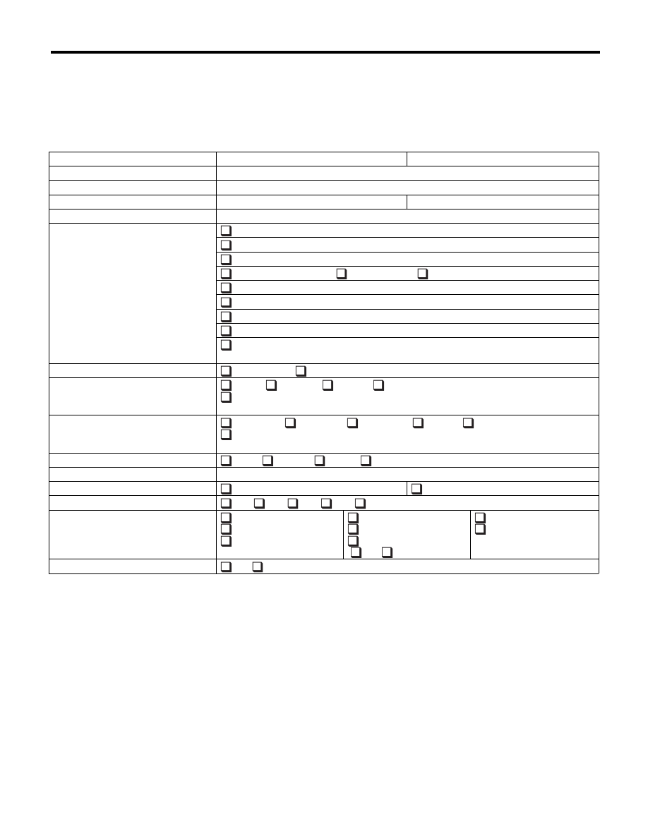
2. Check List for Interview
A: CHECK
Check the following items when a problem has occurred.
NOTE:
Use copies of this page for interviewing customers.
Customer’s name
Date of purchase
Date of repair
Transmission model
Transmission
V.I.N.
Odometer reading
km (miles)
Symptom
No up-shift
No down-shift
No kick down
Vehicle does not move (
Any position
Particular position)
Lock-up malfunction
Noise or vibration
Shift shock or slip
Select lever does not move
Others
(
)
Frequency
Continuous
Intermittent (
times a day)
Weather
Fine
Cloudy
Rainy
Snowy
Others
(
)
Place
Highland
Suburbs
Inner city
Uphill
Rough road
Others
(
)
Ambient air temperature
Hot
Warm
Cool
Cold
Vehicle speed
km/h (MPH)
AT warning light (AT OIL TEMP light)
Blinks continuously
Does not blink
Select lever position
P
R
N
D
Manual mode
Driving condition
Not affected
At racing
While decelerating
At starting
While accelerating
While turning
(
RH/
LH)
While idling
While cruising
Manual mode
ON
OFF
5AT(diag)-5
General Description
AUTOMATIC TRANSMISSION (DIAGNOSTICS)
3. General Description
A: CAUTION
1. SUPPLEMENTAL RESTRAINT SYSTEM
“AIRBAG”
The airbag system wiring harness is routed near
the TCM.
CAUTION:
• All the airbag system wiring harnesses and
connectors are colored yellow. Do not use an
electric test equipment to check these circuits.
• Be careful not to damage the airbag system
wiring harness when performing diagnostics or
servicing the TCM.
2. MEASUREMENT
When measuring the voltage and resistance of the
ECM, TCM or each sensor, use a tapered pin with
a diameter of less than 0.64 mm (0.025 in) in order
to avoid poor contact. Do not insert a pin of more
than 0.65 mm (0.026 in) diameter.
B: INSPECTION
1. BATTERY
Measure the battery voltage and specific gravity of
the electrolyte.
Standard voltage:
12 V or more
Specific gravity:
1.260 or more
2. TRANSMISSION GROUND
Make sure that the ground terminal bolt is tightened
securely.
Tightening torque:
13 N·m (1.3 kgf-m, 9.4 ft-lb)
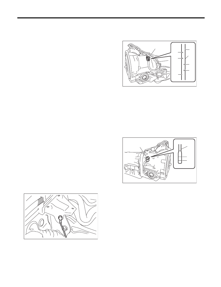
3. ATF LEVEL
Make sure that ATF level is the specified amount.
<Ref. to 5AT-28, INSPECTION, Automatic Trans-
mission Fluid.>
4. FRONT DIFFERENTIAL OIL LEVEL
Make sure the front differential oil level is the spec-
ified amount. <Ref. to 5AT-30, INSPECTION, Dif-
ferential Gear Oil.>
AT-01464
(A) Oil level gauge
(B) Inspection position when “HOT”
(C) Upper level
(D) Lower level
(E) Inspection position when “COLD”
(A) Oil level gauge
(B) Upper level
(C) Lower level
(A)
PI-00362
COLD
LF
HOT
LF
(A)
(B)
(D)
(E)
(D)
(C)
(C)
PI-00184
(A)
(C)
(B)
(A)
F
L
5AT(diag)-6
General Description
AUTOMATIC TRANSMISSION (DIAGNOSTICS)
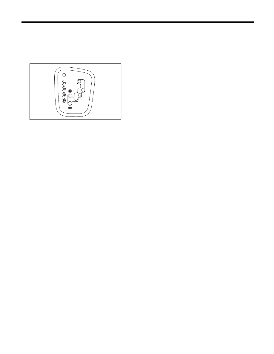
5. OPERATION OF SHIFT SELECT LEVER
Make sure there is no noise, dragging or contact
pattern in each select lever range.
WARNING:
Stop the engine while checking operation of the
select lever.
AT-02048
Нет комментариевНе стесняйтесь поделиться с нами вашим ценным мнением.
Текст