Subaru Legacy III (2000-2003 year). Service manual — part 705
ABS-38
ABS (DIAGNOSTICS)
DIAGNOSTICS CHART WITH DIAGNOSIS CONNECTOR
D: DTC 21 ABNORMAL ABS SENSOR (OPEN CIRCUIT OR INPUT VOLTAGE
TOO HIGH) (FRONT RH)
NOTE:
For the diagnostic procedure, refer to DTC 27. <Ref. to ABS-40, DTC 27 ABNORMAL ABS SENSOR (OPEN
CIRCUIT OR INPUT VOLTAGE TOO HIGH) (REAR LH), Diagnostics Chart with Diagnosis Connector.>
E: DTC 23 ABNORMAL ABS SENSOR (OPEN CIRCUIT OR INPUT VOLTAGE
TOO HIGH) (FRONT LH)
NOTE:
For the diagnostic procedure, refer to DTC 27. <Ref. to ABS-40, DTC 27 ABNORMAL ABS SENSOR (OPEN
CIRCUIT OR INPUT VOLTAGE TOO HIGH) (REAR LH), Diagnostics Chart with Diagnosis Connector.>
F: DTC 25 ABNORMAL ABS SENSOR (OPEN CIRCUIT OR INPUT VOLTAGE
TOO HIGH) (REAR RH)
NOTE:
For the diagnostic procedure, refer to DTC 27. <Ref. to ABS-40, DTC 27 ABNORMAL ABS SENSOR (OPEN
CIRCUIT OR INPUT VOLTAGE TOO HIGH) (REAR LH), Diagnostics Chart with Diagnosis Connector.>
ABS-39
ABS (DIAGNOSTICS)
DIAGNOSTICS CHART WITH DIAGNOSIS CONNECTOR
MEMO:
ABS-40
ABS (DIAGNOSTICS)
DIAGNOSTICS CHART WITH DIAGNOSIS CONNECTOR
G: DTC 27 ABNORMAL ABS SENSOR (OPEN CIRCUIT OR INPUT VOLTAGE
TOO HIGH) (REAR LH)
DIAGNOSIS:
• Faulty ABS sensor (Broken wire, input voltage too high)
• Faulty harness connector
TROUBLE SYMPTOM:
• ABS does not operate.
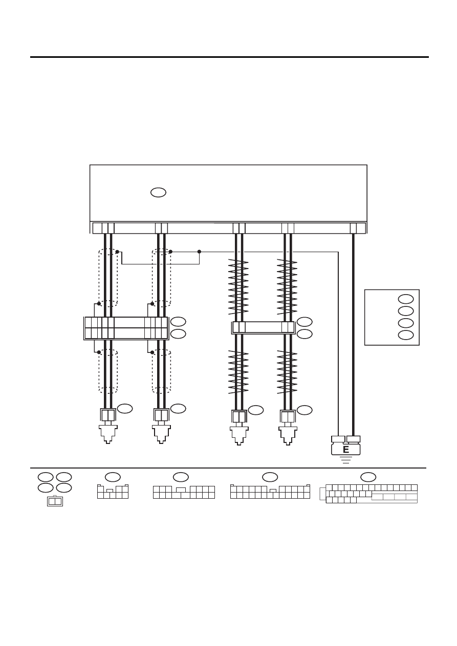
WIRING DIAGRAM:
ABS00309
R73
R72
F49
FRONT
ABS
SENSOR LH
FRONT
ABS
SENSOR RH
ABS CONTROL MODULE AND HYDRAULIC CONTROL UNIT
F49
2
1
1 2 3 4 5 6 7 8 9 10 11 12 13 14 15
16 17 18 19 20 21 22
27 28 29 30 31
23
24
25
26
9
10
11
12
1
2
1
2
1
4
7
8
1
2
5
6
14
15
1
2
23
F55
R49
B15
B6
R73
R72
REAR
ABS
SENSOR LH
REAR
ABS
SENSOR RH
B6
B15
F55
15
16
14
12
13
17
8
9
13
11
12
10
F45
1
*
2
*
RHD
LHD
1
*
2
*
: LHD
RHD
: LHD
RHD B100
B62
F2
F45
1 2 3
4 5 6 7
8 9 10 11
12 13 14 15 16
1
2 3
4 5 6 7 8
F2
3 4
1 2
8 9 10 11
12 13 14 15 16 17 18 19 20 21 22 23 24
5 6
7

ABS-41
ABS (DIAGNOSTICS)
DIAGNOSTICS CHART WITH DIAGNOSIS CONNECTOR
Step
Value
Yes
No
1
CHECK ABS SENSOR.
1) Turn ignition switch to OFF.
2) Disconnect connector from ABS sensor.
3) Measure resistance of ABS sensor connec-
tor terminals.
Terminal
Front RH No. 1 — No. 2:
Front LH No. 1 — No. 2:
Rear RH No. 1 — No. 2:
Rear LH No. 1 — No. 2:
Is the measured value within the specified
range?
1 - 1.5 k
Ω
Replace ABS sen-
sor. Front: <Ref.
to ABS-12, Front
ABS Sensor.>
Rear: <Ref. to
ABS-15, Rear
ABS Sensor.>
2
CHECK BATTERY SHORT OF ABS SEN-
SOR.
1) Disconnect connector from ABSCM&H/U.
2) Measure voltage between ABS sensor and
chassis ground.
Terminal
Front RH No. 1 (+) — Chassis ground (
−−−−
):
Front LH No. 1 (+) — Chassis ground (
−−−−
):
Rear RH No. 1 (+) — Chassis ground (
−−−−
):
Rear LH No. 1 (+) — Chassis ground (
−−−−
):
Is the measured value less than the speci-
fied value?
1 V
Replace ABS sen-
sor. Front: <Ref.
to ABS-12, Front
ABS Sensor.>
Rear: <Ref. to
ABS-15, Rear
ABS Sensor.>
3
CHECK BATTERY SHORT OF ABS SEN-
SOR.
1) Turn ignition switch to ON.
2) Measure voltage between ABS sensor and
chassis ground.
Terminal
Front RH No. 1 (+) — Chassis ground (
−−−−
):
Front LH No. 1 (+) — Chassis ground (
−−−−
):
Rear RH No. 1 (+) — Chassis ground (
−−−−
):
Rear LH No. 1 (+) — Chassis ground (
−−−−
):
Is the measured value less than the speci-
fied value?
1 V
Replace ABS sen-
sor. Front: <Ref.
to ABS-12, Front
ABS Sensor.>
Rear: <Ref. to
ABS-15, Rear
ABS Sensor.>
4
CHECK HARNESS/CONNECTOR BETWEEN
ABSCM&H/U AND ABS SENSOR.
1) Turn ignition switch to OFF.
2) Connect connector to ABS sensor.
3) Measure resistance between ABSCM&H/U
connector terminals.
Connector & terminal
DTC 21 / (F49) No. 11 — No. 12:
DTC 23 / (F49) No. 9 — No. 10:
DTC 25 / (F49) No. 14 — No. 15:
DTC 27 / (F49) No. 7 — No. 8:
Is the measured value within the specified
range?
1 - 1.5 k
Ω
Repair harness/
connector
between
ABSCM&H/U and
ABS sensor.
Нет комментариевНе стесняйтесь поделиться с нами вашим ценным мнением.
Текст