Subaru Legacy III (2000-2003 year). Service manual — part 704

ABS-34
ABS (DIAGNOSTICS)
DIAGNOSTICS CHART WITH DIAGNOSIS CONNECTOR
8
CHECK ABSCM&H/U TERMINAL.
1) Turn ignition switch to OFF.
2) Check for damage at the ABSCM&H/U ter-
minal.
Is the any damage on termianl?
There is no damage on termi-
nal.
Replace
ABSCM&H/U.
<Ref. to ABS-6,
ABS Control Mod-
ule and Hydraulic
Control Unit
(ABSCM&H/U).>
9
CHECK ABSCM&H/U.
Measure resistance between ABSCM&H/U ter-
minals.
Terminal
No. 22 — No. 23:
Does the measured value exceed the specified
value?
1 M
Ω
Replace
ABSCM&H/U.
<Ref. to ABS-6,
ABS Control Mod-
ule and Hydraulic
Control Unit
(ABSCM&H/U).>
10
CHECK WIRING HARNESS.
Measure resistance between connector (F45)
or (F2) and chassis ground.
Connector & terminal
LHD: (F45) No. 5 — Chassis ground:
RHD: (F2) No. 18 — Chassis ground (
−−−−
):
Is the measured value less than the specified
value?
0.5
Ω
Repair harness.
11
CHECK WIRING HARNESS.
1) Connect connector to ABSCM&H/U.
2) Measure resistance between connector
(F45) or (F2) and chassis ground.
Connector & terminal
LHD: (F45) No. 5 — Chassis ground:
RHD: (F2) No. 18 — Chassis ground (
−−−−
):
Is the measured value within the specified
range?
1 M
Ω
Repair harness.
12
CHECK POOR CONTACT IN ABSCM&H/U
CONNECTOR.
Is there poor contact in ABSCM&H/U connec-
tor?
There is no poor contact.
Repair connector.
Replace
ABSCM&H/U.
<Ref. to ABS-6,
ABS Control Mod-
ule and Hydraulic
Control Unit
(ABSCM&H/U).>
Step
Value
Yes
No
ABS-35
ABS (DIAGNOSTICS)
DIAGNOSTICS CHART WITH DIAGNOSIS CONNECTOR
MEMO:
ABS-36
ABS (DIAGNOSTICS)
DIAGNOSTICS CHART WITH DIAGNOSIS CONNECTOR
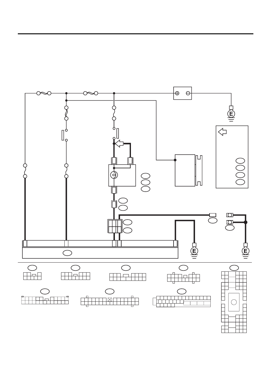
C: DIAGNOSTIC TROUBLE CODE (DTC) DOES NOT APPEAR.
DIAGNOSIS:
• Diagnosis circuit is open.
TROUBLE SYMPTOM:
• The ABS warning light turns on or off normally but the start code cannot be read out in the diagnostic mode.
WIRING DIAGRAM:
ABS00308
24
1
23
5
4
18
20
22
4
ABS CONTROL MODULE AND HYDRAULIC CONTROL UNIT
F49
B82
B81
8
DIAGNOSIS
TERMINAL
DIAGNOSIS
CONNECTOR
B36
B4 B5 B6
A4 A5 A6
C5 C6
F6
D4 D5 D6
F1
H1
C4
G6
G1
C2
K1
M1 M2
K6
L1
D1 D2
A1 A2
B1 B2
I6
J6
L2
I1
J1
H6
M4 M5 M6
L4 L5 L6
N5 N6
O4 O5 O6
N4
P4 P5
N2
O1 O2
P1 P2
N3
O3
P3
P6
A3
B3
C3
E4 E5 E6
E1 E2
i10
1 2 3 4 5 6 7
8 9 10 11 12 13 14
15 16 17 18 19 20 21 22 23 24 25 26 27 28 29 30
1 2 3 4 5 6 7 8 9 10 11 12 13 14 15
16 17 18 19 20 21 22
27 28 29 30 31
23
24
25
26
F49
B82
1 2
4 5 6 7
3
8
i12
1 2 3
4 5 6
7 8 9 10 11 12 13 14
NO
. 8 30A
NO
. 18 15A
BATTERY
SBF-1 100A
SBF-3 50A
SBF-4 50A
IGNITION
SWITCH
COMBINATION
METER
ABS
WARNING
LIGHT
B:
i11
C:
i12
A:
i10
G1
i1
B36
GENERATOR
B5
IGNITION
RELAY
NO
. 5 15A
F45
1 2 3
4 5 6 7
8 9 10 11
12 13 14 15 16
TB
1
*
2
*
3
*
4
*
RHD
LHD
1
*
2
*
3
*
:TURBO A8
NA C3
: LHD
RHD
: TURBO B2
NA C11
: TURBO
ENGINE
MODEL
4
*
: LHD
RHD
TB
F2
F45
B100
B62
1 2 3
8 9 10
4
11 12 13 14 15 16
5 6 7
B:
i11
F2
3 4
1 2
8 9 10 11
12 13 14 15 16 17 18 19 20 21 22 23 24
5 6
7

ABS-37
ABS (DIAGNOSTICS)
DIAGNOSTICS CHART WITH DIAGNOSIS CONNECTOR
Step
Value
Yes
No
1
CHECK DIAGNOSIS TERMINAL.
1) Turn ignition switch to OFF.
2) Measure resistance between diagnosis ter-
minals (B81) and chassis ground.
Terminals
Diagnosis terminal (A) — Chassis
ground:
Diagnosis terminal (B) — Chassis
ground:
Is the measured value less than the speci-
fied value?
0.5
Ω
Repair diagnosis
terminal harness.
2
CHECK DIAGNOSIS LINE.
1) Turn ignition switch to OFF.
2) Connect diagnosis terminal (B81) to diag-
nosis connector (B82) No. 8.
3) Disconnect connector from ABSCM&H/U.
4) Measure resistance between ABSCM&H/U
connector and chassis ground.
Connector & terminal
(F49) No. 4 — Chassis ground:
Is the measured value less than the speci-
fied value?
0.5
Ω
Repair harness
connector
between
ABSCM&H/U and
diagnosis connec-
tor.
3
CHECK POOR CONTACT IN ABSCM&H/U
CONNECTOR.
Is there poor contact in ABSCM&H/U connec-
tor?
There is no poor contact.
Repair connector.
Replace
ABSCM&H/U.
<Ref. to ABS-6,
ABS Control Mod-
ule and Hydraulic
Control Unit
(ABSCM&H/U).>
Нет комментариевНе стесняйтесь поделиться с нами вашим ценным мнением.
Текст