Subaru Legacy III (2000-2003 year). Service manual — part 738
VDC-20
VDC
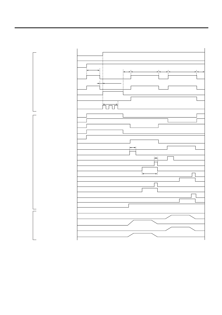
VDC SEQUENCE CONTROL
3. CONDITIONS FOR VDC SEQUENCE CONTROL
NOTE:
• When select monitor is used, control operation starts at point A. The patterns from IGN key ON to the point
A show that operation is started by diagnosis connector.
• HIGH means high voltage.
• LOW means low voltage.
VDC00087
Speed of all wheels
Terminal No. 5 and No. 8
Ignition key switch
ABS warning light
VDC warning light
VDC. OFF indicator light
Pressure sensor signal
AET
AEB
AEC
EAM
Valve relay
Secondary cut valve
Primary cut valve
Secondary suction valve
Primary suction valve
FL outlet valve
FL inlet valve
FR outlet valve
FR inlet valve
RR outlet valve
RR inlet valve
RL outlet valve
RL inlet valve
Pump motor
Pressure of master cylinder
Pressure of RL wheel cylinder
Pressure of FL wheel cylinder
Pressure of RR wheel cylinder
Pressure of FR wheel cylinder
VDC operation indicator light
Operational
guide line of
sequence
control
Operational
pattern of
sequence
control
Operational
pressure of
sequence
control
2.75 km/h (2 MPH) or less
LOW
OFF
OFF
LIGHT
Within 0.5s
Point A
OFF
OFF
OFF
OFF
LIGHT
LIGHT
LIGHT
LOW
HIGH
LOW
HIGH
LOW
HIGH
LOW
HIGH
OFF
OFF
ON
OFF
ON
OFF
ON
OFF
ON
OFF
ON
OFF
ON
OFF
ON
OFF
ON
OFF
ON
OFF
ON
OFF
ON
OFF
ON
OFF
ON
ON
1.5s
1s
10 km/h (6 MPH) or less
ON (Engine run)
0.8s
Within 0.4s
Within 3s
0.4s
1.6s
1.6s
1s
3.4s
3.4s
ON
VDC-21
VDC
VDC SEQUENCE CONTROL
B: SPECIFICATION
1. CONDITIONS FOR COMPLETION OF
VDC SEQUENCE CONTROL
When the following conditions develop, the VDC
sequence control stops and VDC operation is re-
turned to the normal control mode.
1) When the speed of at least one wheel reaches
10 km/h (6 MPH).
2) When terminal No. 5 or No. 8 are separated from
diagnosis terminals. (When select monitor is not
used.)
3) When the brake pedal is pressed during se-
quence control and the braking lamp switch is set
to on.
4) When brake pedal is depressed after ignition key
is turned to ON, and before VDC warning light goes
out. (When select monitor is not used.)
5) When brake pedal is not depressed after ignition
key is turned to ON, and within 0.5 seconds after
VDC warning light goes out. (When select monitor
is not used.)
6) After completion of the sequence control.
7) When malfunction is detected. (When select
monitor is used.)
VDC-22
VDC
YAW RATE AND LATERAL G SENSOR
6. Yaw Rate and Lateral G Sen-
sor
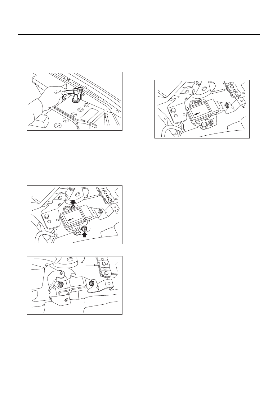
A: REMOVAL
1) Disconnect battery ground cable.
2) Remove console cover.
<Ref. to EI-34, Console Box.>
3) Disconnect connector from yaw rate and lateral
G sensor.
4) Remove yaw rate and lateral G sensor.
CAUTION:
Do not drop or bump yaw rate and lateral G sen-
sor.
5) Remove bracket from body.
B: INSTALLATION
Install in the reverse order of removal.
NOTE:
Do not install yaw rate and lateral G sensor in the
wrong direction. There is an arrow on the sensor
showing which side faces the front of the vehicle.
CAUTION:
After completion of installation procedure, the
following two position settings must be made.
• Steering angle sensor center positioning
• Yaw rate and lateral G sensor 0 positioning
These procedures are necessary for VDCCM to
later recognize what position the vehicle is in.
For procedures for the above two settings,
<Ref. to VDC-9, ADJUSTMENT, VDC Control
Module (VDCCM).>.
FU-00009
VDC00088
VDC00089
VDC00090
VDC-23
VDC
YAW RATE AND LATERAL G SENSOR
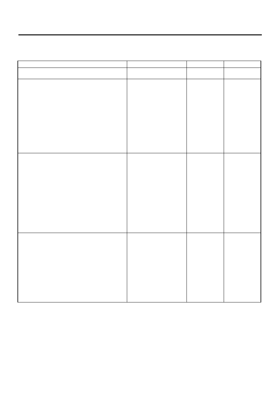
C: INSPECTION
1. LATERAL G SENSOR SIGNAL
Step
Value
Yes
No
1
CHECK SUBARU SELECT MONITOR.
Do you have SUBARU select
Monitor?
2
CHECK YAW RATE AND LATERAL G SEN-
SOR.
1) Move the vehicle to a flat location.
2) Turn ignition switch to OFF.
3) Connect connector to yaw rate and lateral
G sensor.
4) Turn ignition switch to ON.
5) Measure voltage between yaw rate and lat-
eral G sensor connector terminals.
Connector & terminal
(R100) No. 5 (+) — No. 6 (
−−−−
)
Is the voltage within the specified range
when yaw rate and lateral G sensor is hori-
zontal?
2.5
±
0.2 V
Replace yaw rate
and lateral G sen-
sor.
3
CHECK YAW RATE AND LATERAL G SEN-
SOR.
1) Remove yaw rate and lateral G sensor from
vehicle.
2) Measure voltage between yaw rate and lat-
eral G sensor connector terminals.
Connector & terminal
(R100) No. 5 (+) — No. 6 (
−−−−
)
NOTE:
If the yaw rate and lateral G sensor is moved,
the VDC (Yaw rate sensor) may be stored into
the memory.
Is the voltage within the specified range
when yaw rate and lateral G sensor is
inclined right to 90
°
?
3.5
±
0.2 V
Replace yaw rate
and lateral G sen-
sor.
4
CHECK YAW RATE AND LATERAL G SEN-
SOR.
Measure voltage between yaw rate and lateral
G sensor connector terminals.
Connector & terminal
(R100) No. 5 (+) — No. 6 (
−−−−
)
NOTE:
If the yaw rate and lateral G sensor is moved,
the VDC (Yaw rate sensor) may be stored into
the memory.
Is the voltage within the specified range when
yaw rate and lateral G sensor is inclined left to
90
°
?
1.5
±
0.2 V
Replace yaw rate
and lateral G sen-
sor.
Нет комментариевНе стесняйтесь поделиться с нами вашим ценным мнением.
Текст