Subaru Legacy III (2000-2003 year). Service manual — part 736
VDC-12
VDC
HYDRAULIC CONTROL UNIT (H/U)
C: INSPECTION
1) Check connected and fixed condition of connector.
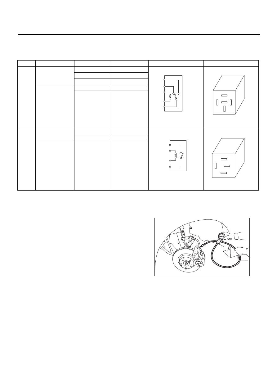
2) Check valve relay and motor relay for discontinuity or short circuits.
1. CHECKING THE HYDRAULIC UNIT ABS
OPERATION BY PRESSURE GAUGE
1) Lift-up vehicle and remove wheels.
2) Disconnect the air bleeder screws from the FL
and FR caliper bodies.
3) Connect two pressure gauges to the FL and FR
caliper bodies.
CAUTION:
• Pressure gauges used exclusively for brake
fluid must be used.
• Do not employ pressure gauge previously
used for transmission since the piston seal is
expanded which may lead to malfunction of the
brake.
NOTE:
Wrap sealing tape around the pressure gauge.
4) Bleed air from the pressure gauges.
5) Perform ABS sequence control.
<Ref. to VDC-16, ABS Sequence Control.>
6) When the hydraulic unit begins to work, and first
the FL side performs decompression, holding, and
compression, and then the FR side performs de-
compression, holding, and compression.
Condition
Terminal number
Standard
Diagram
Terminal location
Valve
relay
Turning off elec-
tricity.
85 — 86
103
±
10
Ω
30 — 87a
Less than 0.5
Ω
30 — 87
More than 1 M
Ω
Turning on elec-
tricity between 85
and 86. (DC 12 V)
30 — 87a
More than 1 M
Ω
30 — 87
Less than 0.5
Ω
Motor
relay
Turning off elec-
tricity.
85 — 86
80
±
10
Ω
30 — 87
More than 1 M
Ω
Turning on elec-
tricity between 85
and 86. (DC 12 V)
30 — 87
Less than 0.5
Ω
VDC00082
87
85
86
30
87a
VDC00083
87
87a
30
86
85
VDC00084
87
85
86
30
VDC00085
87
85
86
30
ABS00134
VDC-13
VDC
HYDRAULIC CONTROL UNIT (H/U)
7) Read values indicated on the pressure gauge
and check if the fluctuation of the values between
decompression and compression meets the stan-
dard values. Also check if any irregular brake pedal
tightness is felt.
8) Remove pressure gauges from FL and FR cali-
per bodies.
9) Remove air bleeder screws from the RL and RR
caliper bodies.
10) Connect the air bleeder screws to the FL and
FR caliper bodies.
11) Connect two pressure gauges to the RL and
RR caliper bodies.
12) Bleed air from the pressure gauges and the FL
and FR caliper bodies.
13) Perform ABS sequence control.
<Ref. to VDC-16, ABS Sequence Control.>
14) When the hydraulic unit begins to work, at first
the RR side performs decompression, holding, and
compression, and then the RL side performs de-
compression, holding, and compression.
15) Read values indicated on the pressure gauges
and check if they meet the standard values.
16) After checking, remove the pressure gauges
from caliper bodies.
17) Connect the air bleeder screws to RL and RR
caliper bodies.
18) Bleed air from brake line.
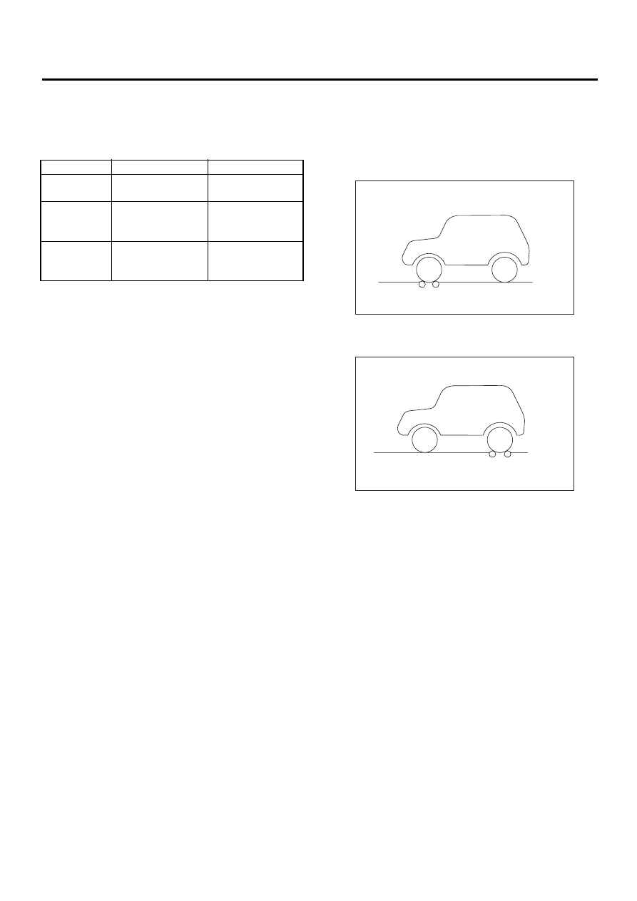
2. CHECKING THE HYDRAULIC UNIT ABS
OPERATION WITH BRAKE TESTER
1) Prepare for operating ABS sequence control.
<Ref. to VDC-16, ABS Sequence Control.>
2) Set the front wheels or rear wheels on the brake
tester and set the select lever's position at “neutral”.
3) Operate the brake tester.
4) Perform ABS sequence control.
<Ref. to VDC-16, ABS Sequence Control.>
5) When the hydraulic unit begins to work, check
the following working sequence.
(1) The FL wheel performs decompression,
holding, and compression in sequence, and
subsequently the FR wheel repeats the cycle.
(2) The RR wheel performs decompression,
holding, and compression in sequence, and
subsequently the RL wheel repeats the cycle.
Front wheel
Rear wheel
Initial value
3,432 kPa
(35 kg/cm
2
, 498 psi)
3,432 kPa
(35 kg/cm
2
, 498 psi)
When
decom-
pressed
490 kPa
(5 kg/cm
2
, 71 psi)
or less
490 kPa
(5 kg/cm
2
, 71 psi)
or less
When
compressed
3,432 kPa
(35 kg/cm
2
, 498 psi)
or more
3,432 kPa
(35 kg/cm
2
, 498 psi)
or more
(1) Brake tester
(1) Brake tester
( 1 )
ABS00136
( 1 )
ABS00137
VDC-14
VDC
HYDRAULIC CONTROL UNIT (H/U)
6) Read values indicated on the brake tester and
check if the fluctuation of values, when decom-
pressed and compressed, meet the standard val-
ues.
7) After checking, also check if any irregular brake
pedal tightness is felt.
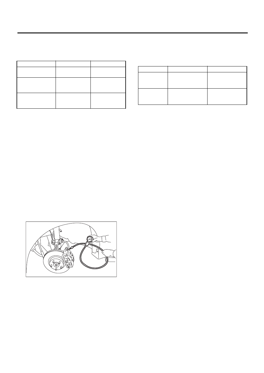
3. CHECKING THE HYDRAULIC UNIT VDC
OPERATION BY PRESSURE GAUGE
1) Lift-up vehicle and remove wheels.
2) Disconnect the air bleeder screws from the FL
and FR caliper bodies.
3) Connect two pressure gauges to the FL and FR
caliper bodies.
CAUTION:
• Pressure gauges used exclusively for brake
fluid must be used.
• Do not employ pressure gauge previously
used for transmission since the piston seal is
expanded which may lead to malfunction of the
brake.
NOTE:
Wrap sealing tape around the pressure gauge.
4) Bleed air from the pressure gauges.
5) Perform VDC sequence control.
<Ref. to VDC-19, VDC Sequence Control.>
6) When the hydraulic unit begins to work, and first
the FL side performs decompression, holding, and
compression, and then the FR side performs de-
compression, holding, and compression.
7) Read values indicated on the pressure gauge
and check if the fluctuation of the values between
decompression and compression meets the stan-
dard values. Also check if any irregular brake pedal
tightness is felt.
8) Remove pressure gauges from FL and FR cali-
per bodies.
9) Remove air bleeder screws from the RL and RR
caliper bodies.
10) Connect the air bleeder screws to the FL and
FR caliper bodies.
11) Connect two pressure gauges to the RL and
RR caliper bodies.
12) Bleed air from the pressure gauges and the FL
and FR caliper bodies.
13) Perform VDC sequence control.
<Ref. to VDC-19, VDC Sequence Control.>
14) When the hydraulic unit begins to work, at first
the RR side performs decompression, holding, and
compression, and then the RL side performs de-
compression, holding, and compression.
15) Read values indicated on the pressure gauges
and check if they meet the standard value.
16) After checking, remove the pressure gauges
from caliper bodies.
17) Connect the air bleeder screws to RL and RR
caliper bodies.
18) Bleed air from brake line.
Front wheel
Rear wheel
Initial value
981 N
(100 kgf, 221 lb)
981 N
(100 kgf, 221 lb)
When
decompressed
490 N
(50 kgf, 110 lb)
or less
490 N
(50 kgf, 110 lb)
or less
When
compressed
981 N
(100 kgf, 221 lb)
or more
981 N
(100 kgf, 221 lb)
or more
ABS00134
Front wheel
Rear wheel
When
compressed
2,942 kPa
(30 kg/cm
2
, 427 psi)
or more
1,961 kPa
(20 kg/cm
2
, 284 psi)
or more
When
decom-
pressed
490 kPa
(5 kg/cm
2
, 71 psi)
or less
490 kPa
(5 kg/cm
2
, 71 psi)
or less
VDC-15
VDC
HYDRAULIC CONTROL UNIT (H/U)
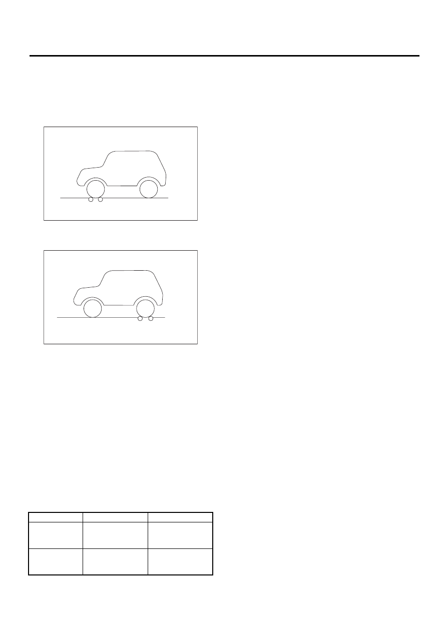
4. CHECKING THE HYDRAULIC UNIT VDC
OPERATION WITH BRAKE TESTER
1) Prepare for operating VDC sequence control.
<Ref. to VDC-19, VDC Sequence Control.>
2) Set the front wheels or rear wheels on the brake
tester and set the select lever's position at “neutral”.
3) Operate the brake tester.
4) Perform ABS sequence control.
<Ref. to VDC-16, ABS Sequence Control.>
5) When the hydraulic unit begins to work, check
the following working sequence.
(1) The FL wheel performs decompression,
holding, and compression in sequence, and
subsequently the FR wheel repeats the cycle.
(2) The RR wheel performs decompression,
holding, and compression in sequence, and
subsequently the RL wheel repeats the cycle.
6) Read values indicated on the brake tester and
check if the fluctuation of values, when decom-
pressed and compressed, meet the standard val-
ues.
7) After checking, also check if any irregular brake
pedal tightness is felt.
(1) Brake tester
(1) Brake tester
Front wheel
Rear wheel
When
compressed
1,961 N
(200 kgf, 441 lb)
or more
981 N
(100 kgf, 221 lb)
or more
When
decompressed
490 N
(50 kgf, 110 lb)
or less
490 N
(50 kgf, 110 lb)
or less
( 1 )
ABS00136
( 1 )
ABS00137
Нет комментариевНе стесняйтесь поделиться с нами вашим ценным мнением.
Текст