Subaru Legacy III (2000-2003 year). Service manual — part 993
CC-4
CRUISE CONTROL SYSTEM
ACTUATOR
2. Actuator
A: REMOVAL
CAUTION:
• Be careful not to apply excessive load to the
wire cable when adjusting and/or installing;
otherwise, the actuator may be deformed or
damaged.
• Do not bend cable sharply with a radius less
than 100 mm (3.94 in); otherwise, cable may
bend permanently, resulting in poor perfor-
mance.
• When installing cable, be careful not to
sharply bend or pinch the inner cable; other-
wise, the cable may break.
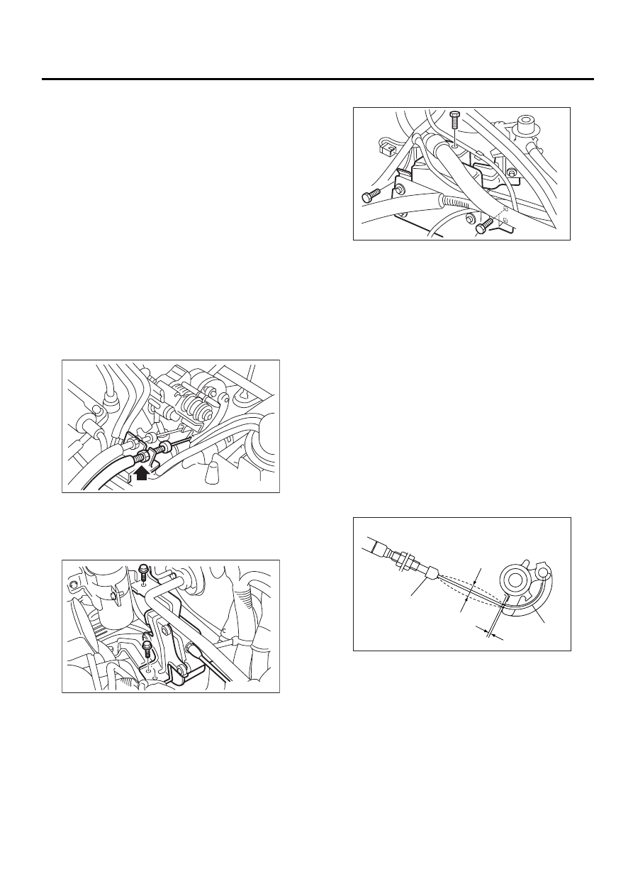
1) Disconnect ground cable from battery.
2) Remove clip bands from cruise control cable.
3) Loosen nut which secures cruise control cable
end to throttle cam and then remove cable from
throttle cam.
4) Remove actuator attaching bolts.
5) Remove actuator while disconnecting connec-
tor.
LHD
RHD
B: INSTALLATION
Install in the reverse order of removal.
Tightening torque:
Actuator
7.4 N·m (0.75 kgf-m, 5.4 ft-lb)
Cable end nut
12 N·m (1,2 kgf-m, 8.7 ft-lb)
NOTE:
Must be adjusted when cable end outer is fixed in
place, so that gap (A) between throttle cam and le-
ver is 0 — 1 mm (0 — 0.04 in), or inner cable de-
flection (D) is 1 — 8 mm (0.039 — 0.315 in) with
specified range of throttle cable play.
(Must be attached while throttle cam is being pulled
by wire cable.)
Must be coated evenly on cam end inner (B) con-
nection.
Cover (C) must be inserted securely, until tip of ca-
ble touches cover stopper.
CC-00085
CC-00086
CC-00125
CC-00037
(B)
(A)
(D)
(C)
CC-5
CRUISE CONTROL SYSTEM
ACTUATOR
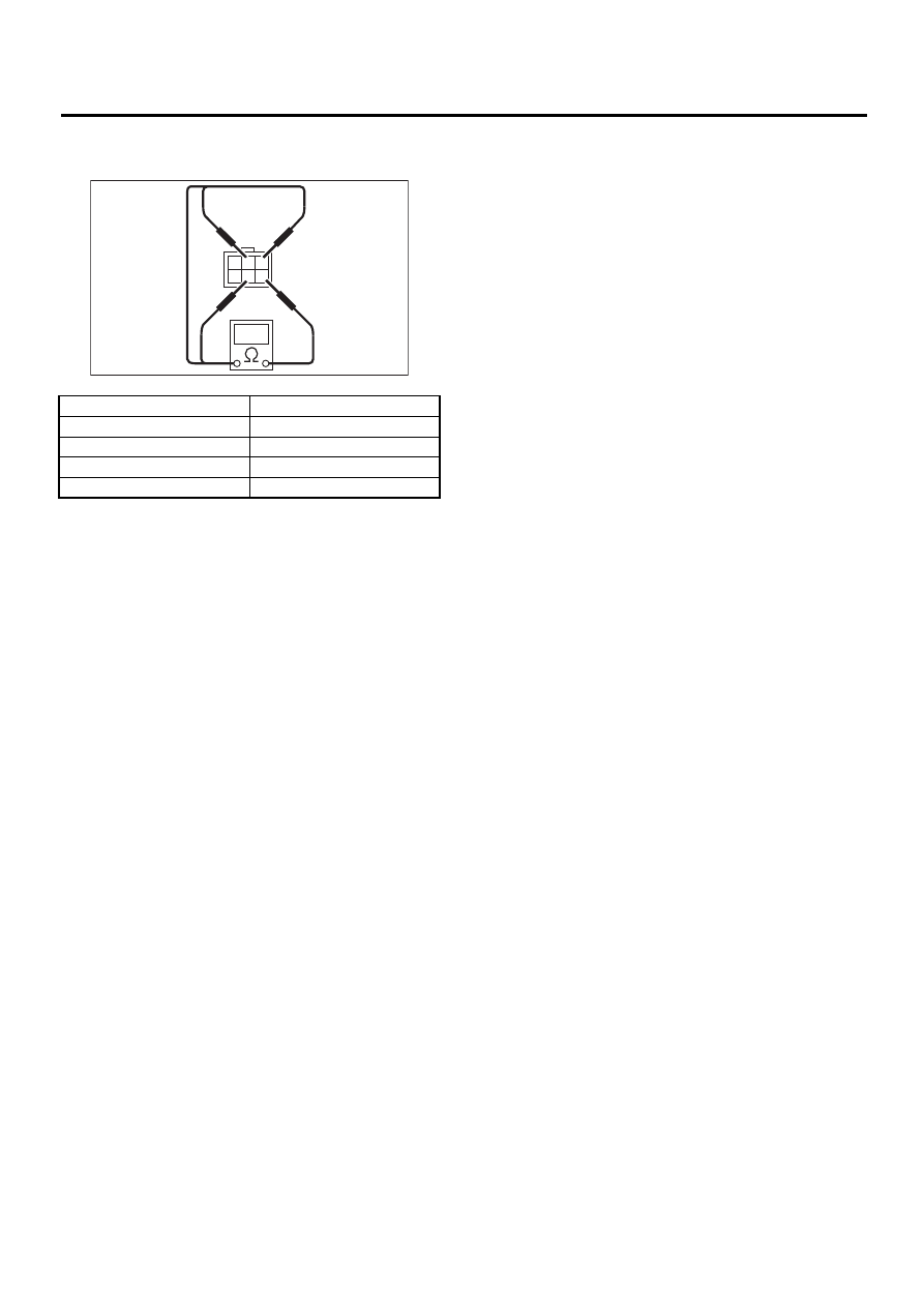
C: INSPECTION
Measure cruise control actuator resistance.
If NG, replace cruise control actuator.
Terminal No.
Standard
4 and 1
Approx. 5
Ω
4 and 2
Approx. 5
Ω
4 and 5
Approx. 5
Ω
3 and 6
Approx. 39
Ω
CC-00012
6
1
2
3
4
5
CC-6
CRUISE CONTROL SYSTEM
CRUISE CONTROL MODULE
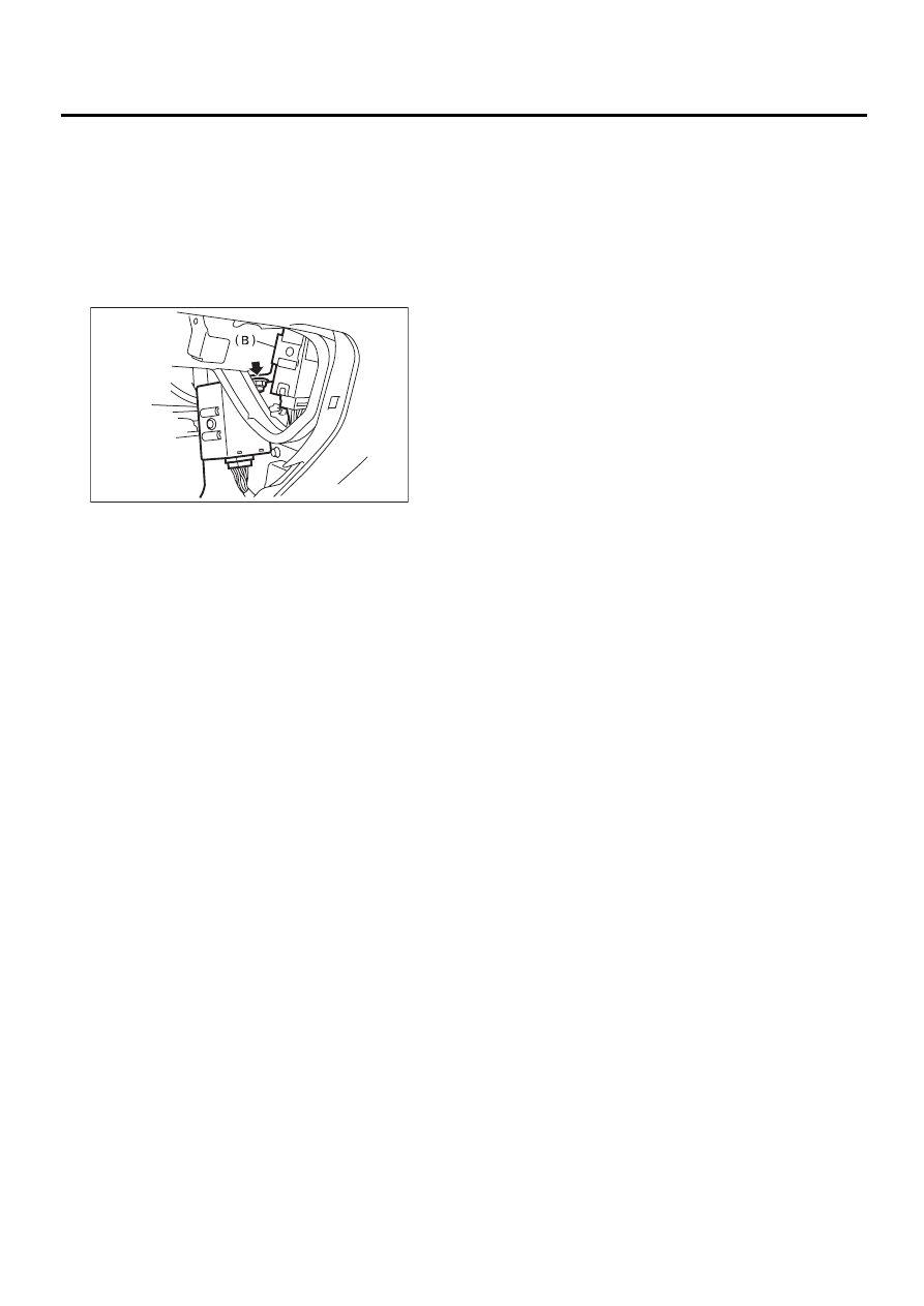
3. Cruise Control Module
A: REMOVAL
1) Disconnect ground cable from battery.
2) Remove glove box. <Ref. to EI-32, REMOVAL,
Glove Box.>
3) Remove nut, then remove cruise control module
(A) and the other electrical control module (B) while
disconnecting connector.
4) Disconnect cruise control module and the other
electrical control module.
B: INSTALLATION
Install is in the reverse order of removal.
CC-00087
( A )
CC-7
CRUISE CONTROL SYSTEM
CRUISE CONTROL MAIN SWITCH
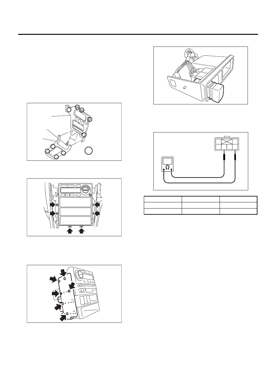
4. Cruise Control Main Switch
A: REMOVAL
1) Disconnect ground cable from battery.
2) Remove screws and clip from instrument panel
lower cover.
3) Remove hook (D) and front cover (A) while dis-
connecting connector.
4) Remove two screws (B) and hook (D), and then
remove center panel (C) while disconnecting con-
nector.
5) Disconnect fifting screws, and slightly pull radio
and switch assembly out from center console.
6) Disconnect electric connectors and antenna-
feeder cord and then disconnect heater controlunit.
7) Remove screw and detach the bracket and then
remove switch panel.
8) Remove main switch by pushing it outward.
B: INSTALLATION
Install is in the reverse order of removal.
C: INSPECTION
If NG, replace cruise control main switch.
CC-00126
:
( A )
( B )
( C )
( D )
CC-00127
CC-00128
Switch position
Terminal No.
Standard
OFF (Released)
3 and 5
More than 1 M
Ω
ON (Pushed)
3 and 5
Less than 1
Ω
CC-00129
CC-00017
1
2
6 5 4 3
Нет комментариевНе стесняйтесь поделиться с нами вашим ценным мнением.
Текст