Subaru Legacy III (2000-2003 year). Service manual — part 685
DS-18
DRIVE SHAFT SYSTEM
FRONT AXLE
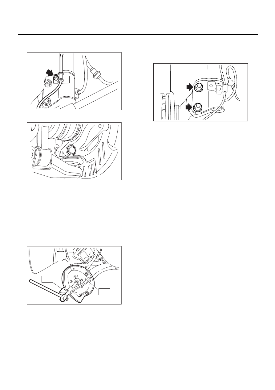
11) Remove bolt which secures sensor harness to
strut.
12) Remove transverse link ball joint from housing.
13) Remove SFJ from transmission spindle.
14) Remove front drive shaft assembly from hub. If
it is hard to remove, use STs.
ST1
926470000
AXLE SHAFT PULLER
ST2
927140000
PLATE
CAUTION:
• Be careful not to damage oil seal lip and tone
wheel when removing front drive shaft.
• When replacing front drive shaft, also replace
inner oil seal.
15) After scribing an alignment mark on camber ad-
justing bolt head, remove bolts which connect
housing and strut, and disconnect housing from
strut.
B: INSTALLATION
1) While aligning alignment mark on camber ad-
justing bolt head, connect housing and strut.
CAUTION:
Use a new self-locking nut.
Tightening torque:
177 N·m (18.0 kgf-m, 130 ft-lb)
2) Install front drive shaft. <Ref. to DS-28, INSTAL-
LATION, Front Drive Shaft.>
3) Install transverse link ball joint to housing.
Tightening torque:
49 N·m (5.0 kgf-m, 36 ft-lb)
4) Install ABS sensor harness on strut.
5) Install ABS sensor on housing.
Tightening torque:
32 N·m (3.3 kgf-m, 23.9 ft-lb)
6) Install disc rotor on hub.
7) Install disc brake caliper on housing.
Tightening torque:
78 N·m (8 kgf-m, 57.9 ft-lb)
DS-00144
DS-00045
DS-00145
ST2
ST1
DS-00046
DS-19
DRIVE SHAFT SYSTEM
FRONT AXLE
8) Connect stabilizer link.
9) Connect tie-rod end ball joint and knuckle arm
with a castle nut, and insert cotter pin into tie-rod
end.
Tightening torque:
27.0 N·m (2.75 kgf-m, 19.9 ft-lb)
10) While depressing brake pedal, tighten axle nut
and lock it securely.
Tightening torque:
216 N·m (22 kgf-m, 159 ft-lb)
CAUTION:
• Use a new axle nut (Olive color).
• Always tighten axle nut before installing
wheel on vehicle. If wheel is installed and
comes in contact with ground when axle nut is
loose, wheel bearings may be damaged.
• Be sure to tighten axle nut to specified
torque. Do not overtighten it as this may dam-
age wheel bearing.
11) After tightening axle nut, lock it securely.
12) Install wheel and tighten wheel nuts to speci-
fied torque.
Tightening torque:
88 N·m (9 kgf-m, 65 ft-lb)
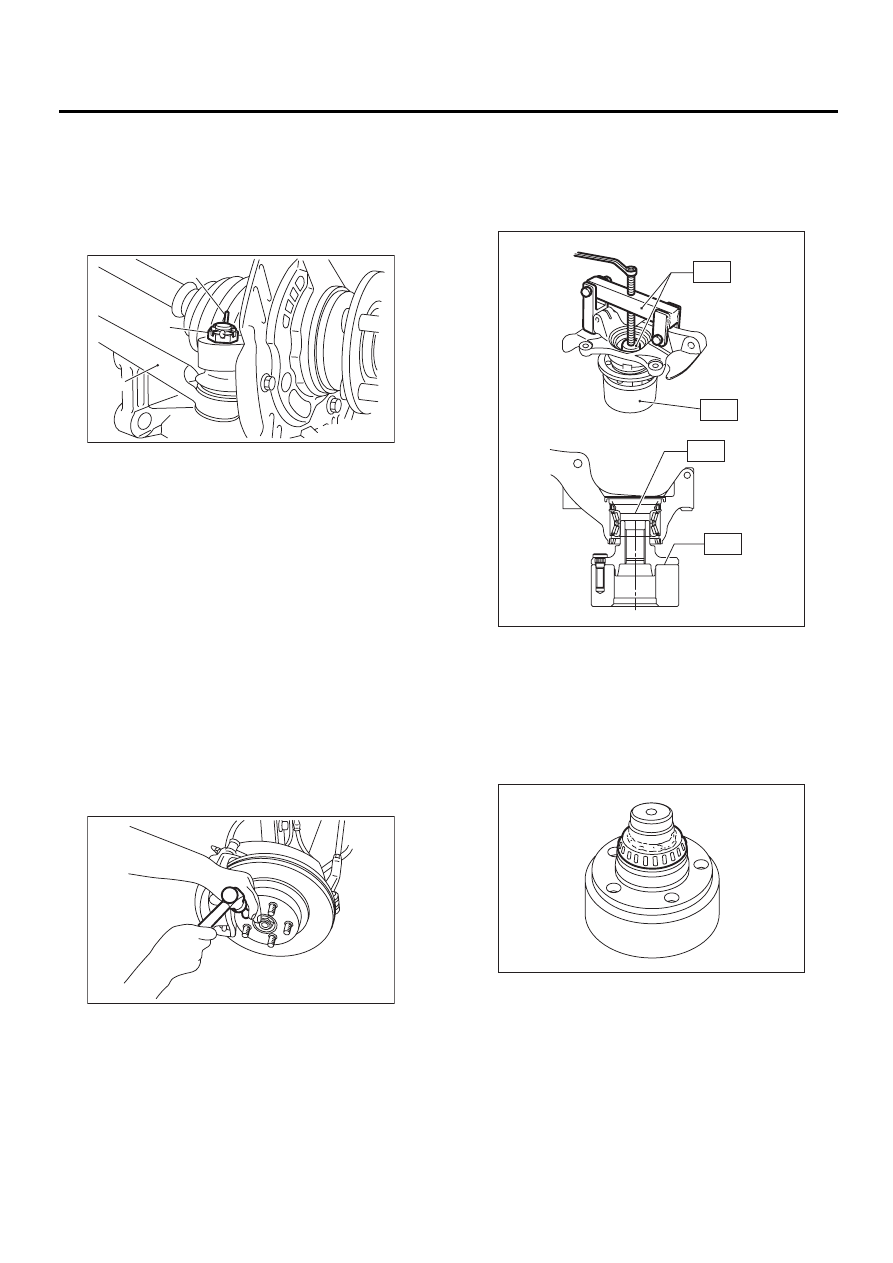
C: DISASSEMBLY
1) Using ST1, support housing and hub securely.
2) Attach ST2 to housing and drive hub out.
ST1
927060000
HUB REMOVER
ST2
927080000
HUB STAND
If inner bearing race remains in the hub, remove it
with a suitable tool (commercially available).
CAUTION:
• Be careful not to scratch polished area of
hub.
• Be sure to install inner race on the side of
outer race from which it was removed.
(A) Cotter pin
(B) Castle nut
(C) Tie-rod
DS-00042
( A )
( B )
( C )
DS-00048
DS-00049
ST1
ST1
ST2
ST2
DS-00050
DS-20
DRIVE SHAFT SYSTEM
FRONT AXLE
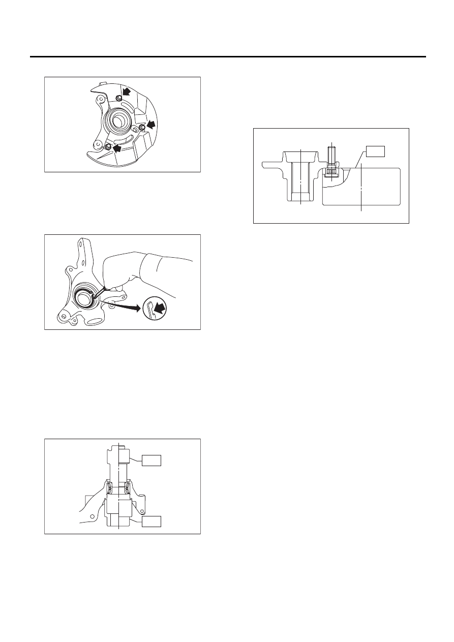
3) Remove disc cover from housing.
4) Using a standard screwdriver, remove outer and
inner oil seals.
CAUTION:
Do not use old oil seals.
5) Using flat-bladed screwdriver, remove snap ring.
6) Using ST1, support housing securely.
7) Using ST2, press inner race to drive out outer
bearing.
ST1
927400000
HOUSING STAND
ST2
927100000
BEARING REMOVER
CAUTION:
• Do not remove outer race unless it is faulty.
• Discard outer race after removal.
• Do not replace inner or outer race separately;
always replace as a unit.
8) Using ST and a hydraulic press, drive hub bolts
out.
ST
927080000
HUB STAND
CAUTION:
Be careful not to hammer hub bolts. This may
deform hub.
DS-00051
DS-00052
DS-00053
ST1
ST2
DS-00054
ST
DS-21
DRIVE SHAFT SYSTEM
FRONT AXLE
D: ASSEMBLY
1) Attach hub to ST securely.
ST
927080000
HUB STAND
2) Using a hydraulic press, press new hub bolts
into place.
CAUTION:
Be sure to press hub bolts until their seating
surfaces contact the hub.
NOTE:
Use 12 mm (0.47 in) dia. holes in HUB STAND to
prevent bolts from tilting.
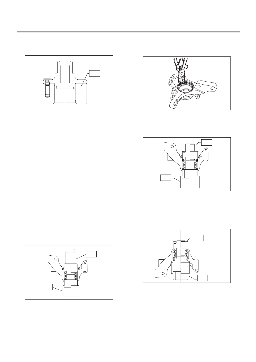
3) Clean dust or foreign particles from inside the
housing.
4) Using ST1 and ST2, press a new bearing into
place.
ST1
927400000
HOUSING STAND
ST2
927100000
BEARING REMOVER
CAUTION:
• Always press outer race when installing bear-
ing.
• Be careful not to remove plastic lock from in-
ner race when installing bearing.
• Charge bearing with new grease when outer
race is not removed.
Specified grease:
SHELL 6459N
5) Using pliers, install snap ring in its groove.
CAUTION:
Make sure to install it firmly to groove.
6) Using ST1 and ST2, press inner oil seal until it
contacts circlip.
ST1
927410000
OIL SEAL INSTALLER
ST2
927400000
HOUSING STAND
7) Invert ST and housing.
ST
927400000
HOUSING STAND
8) Using ST1 and ST2, press outer oil seal until it
contacts the bottom of housing.
ST1
927410000
OIL SEAL INSTALLER
ST2
927400000
HOUSING STAND
DS-00055
ST
DS-00056
ST1
ST2
DS-00057
DS-00059
ST1
ST2
DS-00058
ST1
ST2
Нет комментариевНе стесняйтесь поделиться с нами вашим ценным мнением.
Текст