Subaru Legacy III (2000-2003 year). Service manual — part 515
EN(H4DOSTC)-230
ENGINE (DIAGNOSTICS)
DIAGNOSTIC PROCEDURE WITH DIAGNOSTIC TROUBLE CODE (DTC)
BI: DTC P1250 — RELIEF VALVE CONTROL SOLENOID VALVE 2 CIRCUIT
HIGH —
• TROUBLE SYMPTOM:
• Poor driving performance
CAUTION:
After repair or replacement of faulty parts, conduct Clear Memory Mode <Ref. to EN(H4DOSTC)-35,
OPERATION, Clear Memory Mode.> and Inspection Mode <Ref. to EN(H4DOSTC)-33, Inspection
Mode.> .
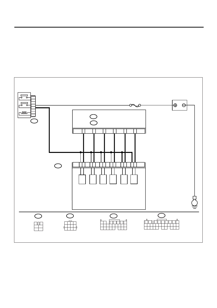
• WIRING DIAGRAM:
EN-00939
B220
B47
E
BATTERY
MAIN RELAY
3
B136
ECM
SBF-5
5
2
1
4
6
B47
3
4
1
2
5
6
B220
SOLENOID
BOX ASSY
1
2
3
4
5
6
7
8
9
10
11
12
(A)
(B)
(C)
(D)
(E)
(F)
(A): RELIEF VALVE SOLENOID 2
(B): RELIEF VALVE SOLENOID 1
(C): EXHAUST VALVE CONTROL SOLENOID VALVE
(NEGATIVE PRESSURE)
(D): EXHAUST VALVE CONTROL SOLENOID VALVE
(POSITIVE PRESSURE)
(E): INTAKE AIR CONTROL SOLENOID VALVE
(F): EXHAUST VALVE CONTROL DUTY SOLENOID VALVE
C:
B137
D:
C11
C12
C3
C1
D22
D11
1 2 3 4
5 6 7 8
9 10 11 12
B136
1 2
7
8 9
5
6
3
4
10 11 12
19 20 21
13 14 15 16
17 18
22 23 24
B137
1
2
7
8
9
5
6
3
4
10 11 12
19 20 21
29 30 31
13 14 15 16 17
27 28
18
22 23 24 25 26

EN(H4DOSTC)-231
ENGINE (DIAGNOSTICS)
DIAGNOSTIC PROCEDURE WITH DIAGNOSTIC TROUBLE CODE (DTC)
Step
Value
Yes
No
1
CHECK INPUT SIGNAL TO ECM.
1) Turn the ignition switch to ON.
2) Measure the voltage between ECM and
chassis ground.
Connector & terminal
(B136) No. 11 (+) — Chassis ground (
−−−−
):
Does the measured value exceed the spec-
ified value?
10 V
2
CHECK POOR CONTACT.
Check poor contact in ECM connector.
Is there poor contact in ECM connector?
There is poor contact.
Repair the poor
contact in ECM
connector.
Replace the ECM.
<Ref. to
FU(H4DOSTC)-
40, Engine Con-
trol Module.>
3
CHECK HARNESS BETWEEN RELIEF
VALVE CONTROL SOLENOID VALVE 2 AND
ECM CONNECTOR.
1) Turn the ignition switch to OFF.
2) Disconnect the connector from relief valve
control solenoid valve 2.
3) Turn the ignition switch to ON.
4) Measure the voltage between ECM and
chassis ground.
Connector & terminal
(B136) No. 11 (+) — Chassis ground (
−−−−
):
Does the measured value exceed the spec-
ified value?
10 V
Repair the battery
short circuit in har-
ness between
ECM and relief
valve control sole-
noid valve 2 con-
nector. After
repair, replace the
ECM. <Ref. to
FU(H4DOSTC)-
40, Engine Con-
trol Module.>
4
CHECK RELIEF VALVE CONTROL SOLE-
NOID VALVE 2.
1) Turn the ignition switch to OFF.
2) Measure the resistance between relief
valve control solenoid valve 2 terminals.
Terminals
No. 1 — No. 2:
Is the measured value less than the speci-
fied value?
1
Ω
Replace the relief
valve control sole-
noid valve 2.
<Ref. to
IN(H4DOSTC)-19,
Solenoid Box
Assembly.> and
replace ECM
<Ref. to
FU(H4DOSTC)-
40, Engine Con-
trol Module.>
5
CHECK POOR CONTACT.
Check poor contact in ECM and relief valve
control solenoid valve 2 connectors.
Are there poor contact in ECM and relief valve
control solenoid valve 2 connectors?
There are poor contacts.
Repair the poor
contact in ECM
and relief valve
control solenoid
valve 2 connec-
tors.
Replace the ECM.
<Ref. to
FU(H4DOSTC)-
40, Engine Con-
trol Module.>
EN(H4DOSTC)-232
ENGINE (DIAGNOSTICS)
DIAGNOSTIC PROCEDURE WITH DIAGNOSTIC TROUBLE CODE (DTC)
BJ:DTC P1507 — IDLE CONTROL SYSTEM MALFUNCTION (FAIL-SAFE) —
• TROUBLE SYMPTOM:
• Engine keeps running at higher revolution than specified idling revolution.
• Fuel is cut according to fail-safe function.
CAUTION:
After repair or replacement of faulty parts, conduct Clear Memory Mode <Ref. to EN(H4DOSTC)-35,
OPERATION, Clear Memory Mode.> and Inspection Mode <Ref. to EN(H4DOSTC)-33, Inspection
Mode.> .
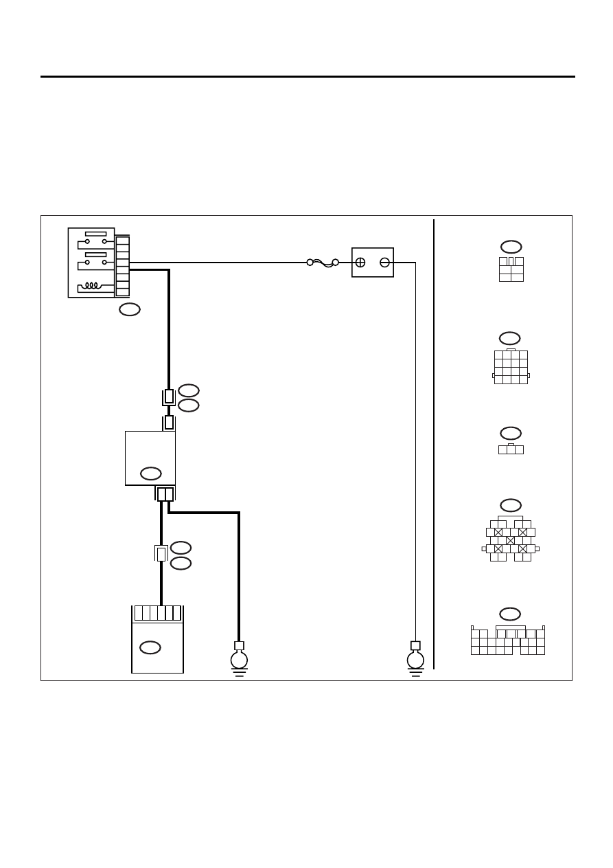
• WIRING DIAGRAM:
EN-00947
BATTERY
MAIN RELAY
E
E
6
4
5
3
2
1
10
IDLE
AIR CONTROL
SOLENOID
VALVE
1
3
E7
B47
B47
3
4
1
2
5
6
1 2
7
8 9
5
6
3
4
10 11 12
19 20 21
13 14 15 16
17 18
22 23 24
B136
B136 ECM
2
1
B22
E3
SBF-5
B22
E7
1 2 3
1 2
5
6 7
8
13
14 15
16
9 10
11 12
3 4
17 18
19 20
1 2 3 4
5 6 7 8
9 10 11 12
13 14 15 16
B21
E2
B21
12

EN(H4DOSTC)-233
ENGINE (DIAGNOSTICS)
DIAGNOSTIC PROCEDURE WITH DIAGNOSTIC TROUBLE CODE (DTC)
Step
Value
Yes
No
1
CHECK ANY OTHER DTC ON DISPLAY.
Is any other DTC displayed?
DTC indicated.
Inspect the rele-
vant DTC using
“List of Diagnostic
Trouble Code
(DTC)”. <Ref. to
EN(H4DOSTC)-
62, List of Diag-
nostic Trouble
Code (DTC).>
NOTE:
In this case, it is
not necessary to
inspect DTC
P0507.
2
CHECK AIR INTAKE SYSTEM.
1) Turn the ignition switch to ON.
2) Start the engine, and idle it.
3) Check the following items:
•Loose installation of intake manifold, idle air
control solenoid valve and throttle body
•Cracks of intake manifold gasket, idle air con-
trol solenoid valve gasket and throttle body
gasket
•Disconnections of vacuum hoses
Is there a fault in the air intake system?
There is no problem.
Repair the air suc-
tion and leaks.
3
CHECK THROTTLE CABLE.
Does the throttle cable have play for adjust-
ment?
Cable has play correctly.
Adjust the throttle
cable. <Ref. to
SP(H4SO)-10,
Accelerator Con-
trol Cable.>
4
CHECK AIR BY-PASS LINE.
1) Turn the ignition switch to OFF.
2) Remove the idle air control solenoid valve
from throttle body. <Ref. to
FU(H4DOSTC)-35, Idle Air Control Sole-
noid Valve.>
3) Confirm that there are no foreign particles
in the by-pass air line.
Are foreign particles in the by-pass air line?
Foreign particles are in the by-
pass air line.
Remove the for-
eign particles from
by-pass air line.
Replace the idle
air control solenoid
valve. <Ref. to
FU(H4DOSTC)-
35, Idle Air Con-
trol Solenoid
Valve.>
Нет комментариевНе стесняйтесь поделиться с нами вашим ценным мнением.
Текст