Subaru Legacy III (2000-2003 year). Service manual — part 516
EN(H4DOSTC)-234
ENGINE (DIAGNOSTICS)
DIAGNOSTIC PROCEDURE WITH DIAGNOSTIC TROUBLE CODE (DTC)
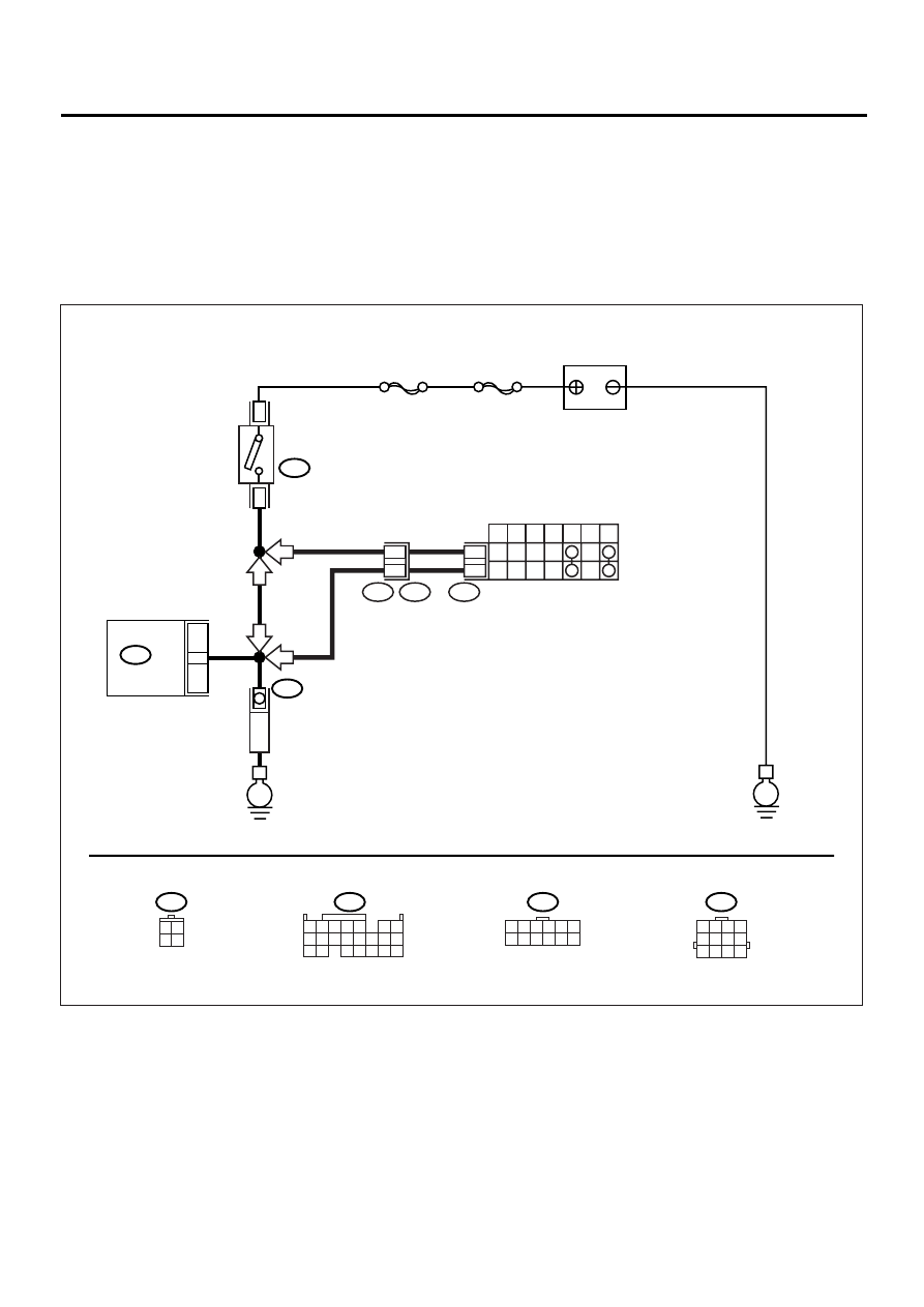
BK:DTC P1518 — STARTER SWITCH CIRCUIT LOW INPUT —
• TROUBLE SYMPTOM:
• Failure of engine to start
CAUTION:
After repair or replacement of faulty parts, conduct Clear Memory Mode <Ref. to EN(H4DOSTC)-35,
OPERATION, Clear Memory Mode.> and Inspection Mode <Ref. to EN(H4DOSTC)-33, Inspection
Mode.> .
• WIRING DIAGRAM:
EN-00930
BATTERY
IGNITION
SWITCH
STARTER
MOTOR
SBF-4
SBF-1
B72
B72
B14
B134 ECM
E
E
1
3
16
3 4
1 2
B134
B12
T7
1 2 3 4
10 11 12
19 20 21
13
5
6
14 15
7
8 9
16 17
18
22
12
INHIBITOR SWITCH
7
P
R
N
D
3
2
1
12
11
T7
T3
B12
AT
AT
MT
MT
1 2 3 4 5 6
7 8 9 10 11 12
1 2 3 4
5 6 7 8
9 10 11 12

EN(H4DOSTC)-235
ENGINE (DIAGNOSTICS)
DIAGNOSTIC PROCEDURE WITH DIAGNOSTIC TROUBLE CODE (DTC)
Step
Value
Yes
No
1
CHECK OPERATION OF STARTER MOTOR.
Does the starter motor operate when ignition
switch to “ST”?
Operates.
Repair the har-
ness and connec-
tor.
NOTE:
In this case, repair
the following:
• Open or ground
short circuit in har-
ness between
ECM and starter
motor connector.
• Poor contact in
ECM connector.
Check the starter
motor circuit. <Ref.
to EN(H4DOSTC)-
52, STARTER
MOTOR CIR-
CUIT, Diagnostics
for Engine Start-
ing Failure.>
EN(H4DOSTC)-236
ENGINE (DIAGNOSTICS)
DIAGNOSTIC PROCEDURE WITH DIAGNOSTIC TROUBLE CODE (DTC)
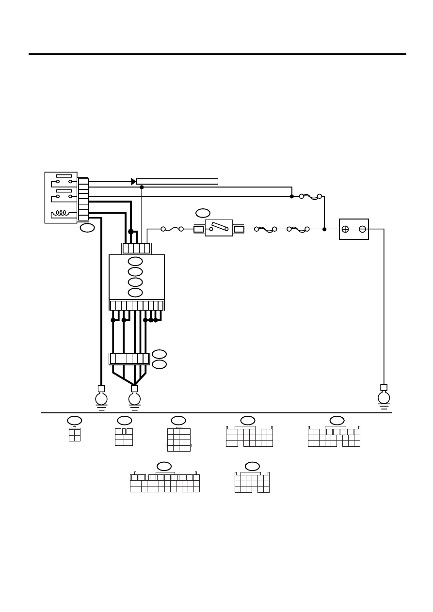
BL:DTC P1560 — BACK-UP VOLTAGE CIRCUIT MALFUNCTION —
CAUTION:
After repair or replacement of faulty parts, conduct Clear Memory Mode <Ref. to EN(H4DOSTC)-35,
OPERATION, Clear Memory Mode.> and Inspection Mode <Ref. to EN(H4DOSTC)-33, Inspection
Mode.> .
• WIRING DIAGRAM:
EN-00931
B72
B137
3 4
1 2
1
2
7
8
9
5
6
3
4
10 11 12
19 20 21
29 30 31
13 14 15 16 17
27 28
18
22 23 24 25 26
BATTERY
IGNITION
SWITCH
MAIN RELAY
SBF-4
SBF-1
SBF-5
B72
TO FRONT OXYGEN(A/F) SENSOR
A2
D8
D9
A22
C17
C8
C18
A7
A15
E1
A12
D2
D3
D10
A14
No.11
B47
E3
B22
1
2
3
5
6
4
ECM
E
E
1
4
B134
B136
B137
A :
C :
D :
B84
E :
3
15
16
14
13
E
3
4
1
2
5
6
1 2 3 4
5 6 7 8
9 10 11 12
13 14 15 16
B134
B22
B47
B84
B136
1 2 3 4
10 11 12
19 20 21
13
5
6
14 15
7
8 9
16 17
18
22
1 2
7
8 9
5
6
3
4
10 11 12
19 20 21
13 14 15 16
17 18
22 23 24
1 2 3
8 9 10
4
11 12
13 14 15
16
5 6
7
17

EN(H4DOSTC)-237
ENGINE (DIAGNOSTICS)
DIAGNOSTIC PROCEDURE WITH DIAGNOSTIC TROUBLE CODE (DTC)
Step
Value
Yes
No
1
CHECK INPUT SIGNAL FOR ECM.
1) Turn the ignition switch to OFF.
2) Measure the voltage between ECM and
chassis ground.
Connector & terminal
(B137) No. 10 (+) — Chassis ground (
−−−−
):
Does the measured value exceed the spec-
ified value?
10 V
Repair the poor
contact in ECM
connector.
2
CHECK HARNESS BETWEEN ECM AND
MAIN FUSE BOX CONNECTOR.
1) Disconnect the connector from ECM.
2) Measure the resistance of harness
between ECM and chassis ground.
Connector & terminal
(B137) No. 10 — Chassis ground:
Does the measured value exceed the spec-
ified value?
1 M
Ω
Repair the ground
short circuit in har-
ness between
ECM connector
and battery termi-
nal.
3
CHECK FUSE SBF-5.
Is the fuse blown?
Fuse is blown-out.
Replace the fuse.
Repair the har-
ness and connec-
tor.
NOTE:
In this case, repair
the following:
• Open circuit in
harness between
ECM and battery
• Poor contact in
ECM connector
• Poor contact in
battery terminal
Нет комментариевНе стесняйтесь поделиться с нами вашим ценным мнением.
Текст