Subaru Legacy III (2000-2003 year). Service manual — part 545
AT-74
AUTOMATIC TRANSMISSION
ATF FILTER
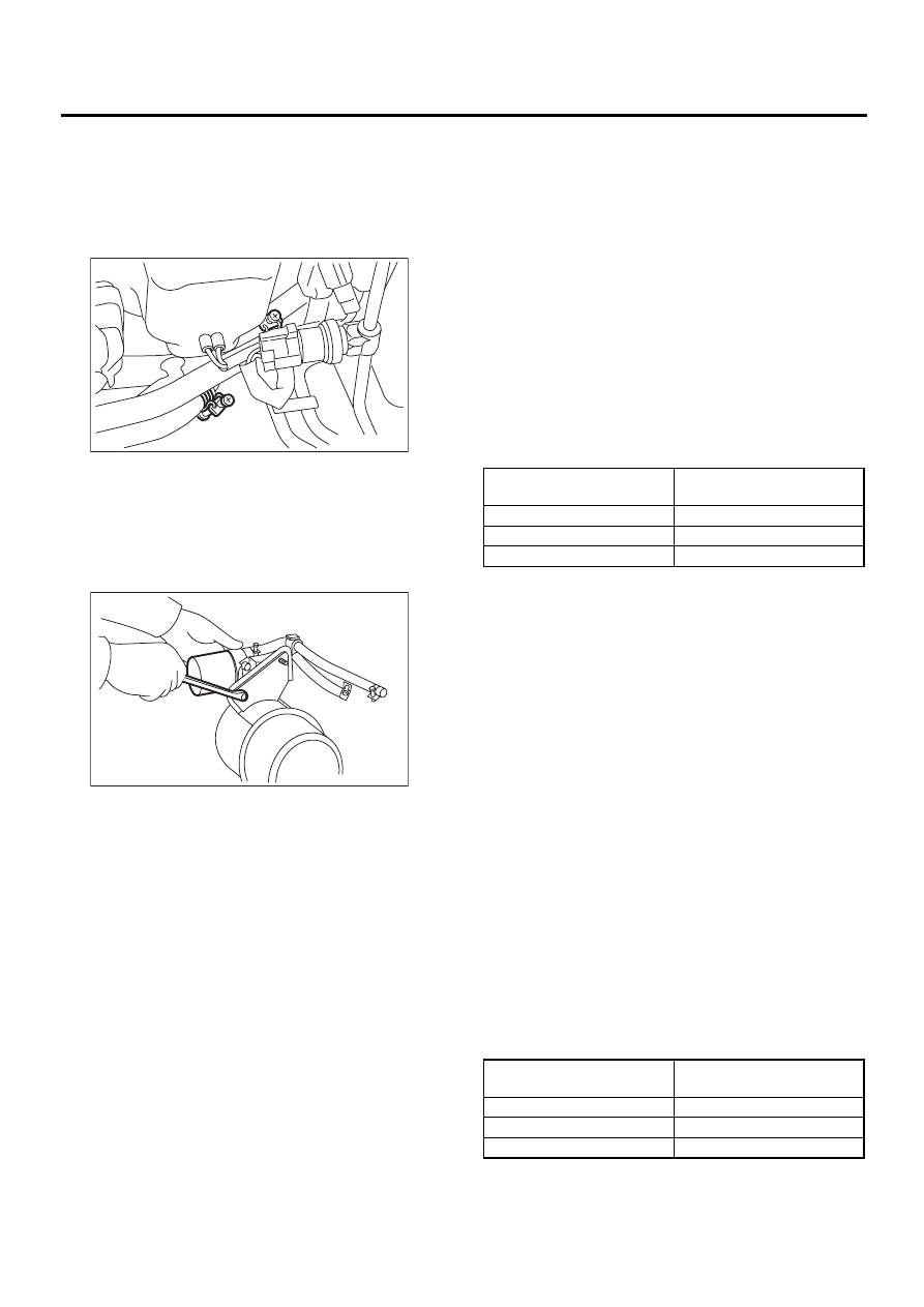
4) Release clamp of IN, OUT of oil filter hose, and
remove hose from pipe.
NOTE:
• Plug the pipe.
• Put a mark etc., to distinguish IN, OUT on pipe
and hose.
5) Lift vehicle and remove front left mud guard.
<Ref. to EI-22, REMOVAL, Mud Guard.>
6) Remove the surge tank.
<Ref. to IN(H4DOSTC)-22, REMOVAL, Surge
Tank.>
7) Remove oil filter assembly.
8) Secure oil filter assembly on a vise, etc and re-
move oil filter using Special Service Tool.
ST
498545400
OIL FILTER WRENCH
B: INSTALLATION
1. EXCEPT 3.0 L MODEL
1) Get new ATF filter and apply a thin coat of ATF
to the oil seal.
2) Install ATF filter. Turn it by hand, being careful
not to damage oil seal.
3) Using ST, tighten ATF filter.
Calculate ATF filter torque specifications using the
following formula.
T2 = L2/(L1 + L2)
×
T1
T1: 14 N·m (1.4 kgf-m, 10.1 ft-lb)
[Required torque setting]
T2: Tightening torque
L1: ST length 0.078 m (3.07 in)
L2: Torque wrench length
Example:
NOTE:
Align ST with torque wrench while tightening ATF
filter.
ST
498545400
OIL FILTER WRENCH
4) Add ATF.
5) Inspect level of ATF. <Ref. to AT-30, Automatic
Transmission Fluid.>
2. 3.0 L MODEL
• ATF Filter
1) Get new ATF filter and apply a thin coat of ATF
to the oil seal.
2) Install AT oil filter. Turn it by hand, being careful
not to damage oil seal.
3) Using ST, tighten AT oil filter.
Calculate AT filter torque specifications using the
following formula.
T2 = L2/(L1 + L2)
×
T1
T1: 14 N·m (1.4 kgf-m, 10.1 ft-lb)
[Required torque setting]
T2: Tightening torque
L1: ST length 0.078 m (3.07 in)
L2: Torque wrench length
Example:
AT-00701
AT-00907
Torque wrench length
mm (in)
Tightening torque
N·m (kgf-m, ft-lb)
100 (3.94)
7.7 (0.79, 5.7)
150 (5.91)
9.0 (0.92, 6.7)
200 (7.87)
10 (1.0, 7.2)
Torque wrench length
mm (in)
Tightening torque
N·m (kgf-m, ft-lb)
100 (3.94)
7.7 (0.79, 5.7)
150 (5.91)
9.0 (0.92, 6.7)
200 (7.87)
10 (1.0, 7.2)

AT-75
AUTOMATIC TRANSMISSION
ATF FILTER
NOTE:
Align ST with torque wrench while tightening AT oil
filter.
ST
498545400
OIL FILTER WRENCH
4) Install front left mud guard. <Ref. to EI-22, IN-
STALLATION, Mud Guard.>
5) Add ATF.
6) Inspect level of ATF. <Ref. to AT-30, Automatic
Transmission Fluid.>
• ATF Filter Assembly
1) Install ATF filter with attachment to bracket.
Tightening torque:
14 N·m (1.4 kgf-m, 10 ft-lb)
2) Install ATF filter assembly to vehicle.
Tightening torque:
16 N·m (1.6 kgf-m, 12 ft-lb)
3) Install AT oil filter. Turn it by hand, being careful
not to damage oil seal.
4) Using ST, tighten AT oil filter.
Calculate AT filter torque specifications using the
following formula.
T2 = L1/(L1 + L2)
×
T1
T1: 14 N·m (1.4 kgf-m, 10.1 ft-lb)
[Required torque setting]
T2: Tightening torque
L1: ST length 0.078 m (3.07 in)
L2: Torque wrench length
Example:
NOTE:
Align ST with torque wrench while tightening AT oil
filter.
ST
498545400
OIL FILTER WRENCH
5) Install hoses to pipe.
NOTE:
Install hoses to pipe aligning marks on them.
6) Install front left mud guard.
<Ref. to EI-22, INSTALLATION, Mud Guard.>
7) Add ATF.
8) Inspect level of ATF. <Ref. to AT-30, Automatic
Transmission Fluid.>
3. TURBO MODEL
1) Get new ATF filter and apply a thin coat of ATF
to the oil seal.
2) Install ATF filter. Turn it by hand, being careful
not to damage oil seal.
3) Using ST, tighten ATF filter.
Calculate ATF filter torque specifications using the
following formula.
T2 = L2/(L1 + L2)
×
T1
T1: 14 N·m (1.4 kgf-m, 10.1 ft-lb)
[Required torque setting]
T2: Tightening torque
L1: ST length 0.078 m (3.07 in)
L2: Torque wrench length
Example:
NOTE:
Align ST with torque wrench while tightening ATF
filter.
ST
498545400
OIL FILTER WRENCH
4) Install oil filter wrench assembly.
Tightening torque:
16 N·m (1.6 kgf-m, 10.1 ft-lb)
5) Install surge tank.
<Ref. to IN(H4DOSTC)-22, INSTALLATION, Surge
Tank.>
6) Remove front left mud guard.
<Ref. to EI-22, INSTALLATION, Mud Guard.>
7) Tighten oil filter bracket mounting bolts.
Tightening torque:
16 N·m (1.6 kgf-m, 10.1 ft-lb)
8) Install hoses to pipe.
NOTE:
Align indicated matching marks between hose and
pipe.
9) Install battery.
10) Inspect level of ATF. <Ref. to AT-30, Automatic
Transmission Fluid.>
C: INSPECTION
Replace the part if any defect is found from the in-
spection.
Check for rust, hole, ATF leaks, and other damage.
Torque wrench length
mm (in)
Tightening torque
N·m (kgf-m, ft-lb)
100 (3.94)
7.7 (0.79, 5.7)
150 (5.91)
9.0 (0.92, 6.7)
200 (7.87)
10 (1.0, 7.2)
Torque wrench length
mm (in)
Tightening torque
N·m (kgf-m, ft-lb)
100 (3.94)
7.7 (0.79, 5.7)
150 (5.91)
9.0 (0.92, 6.7)
200 (7.87)
10 (1.0, 7.2)
AT-76
AUTOMATIC TRANSMISSION
TRANSMISSION CONTROL MODULE (TCM)
20.Transmission Control Mod-
ule (TCM)
A: REMOVAL
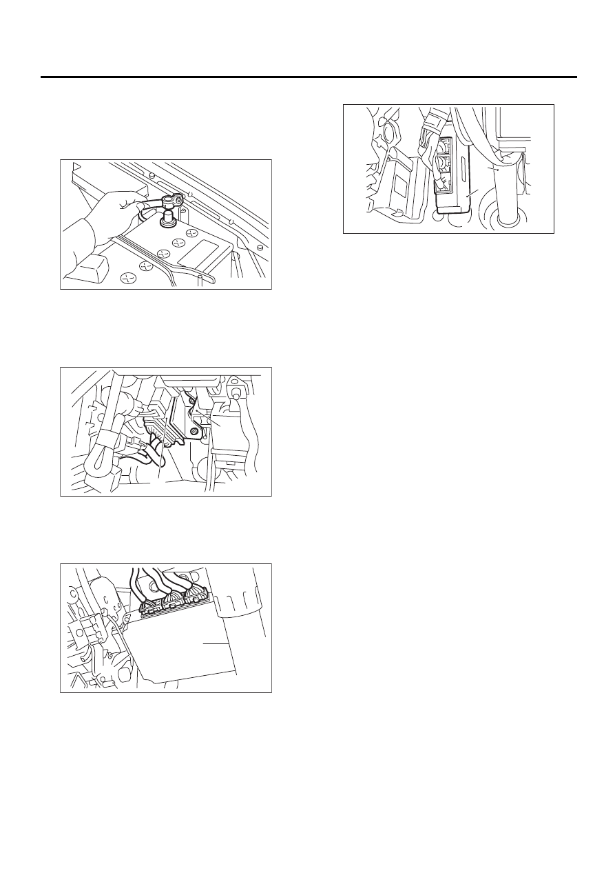
1) Disconnect the ground cable from battery.
2) Remove the lower cover and then disconnect
the connector.
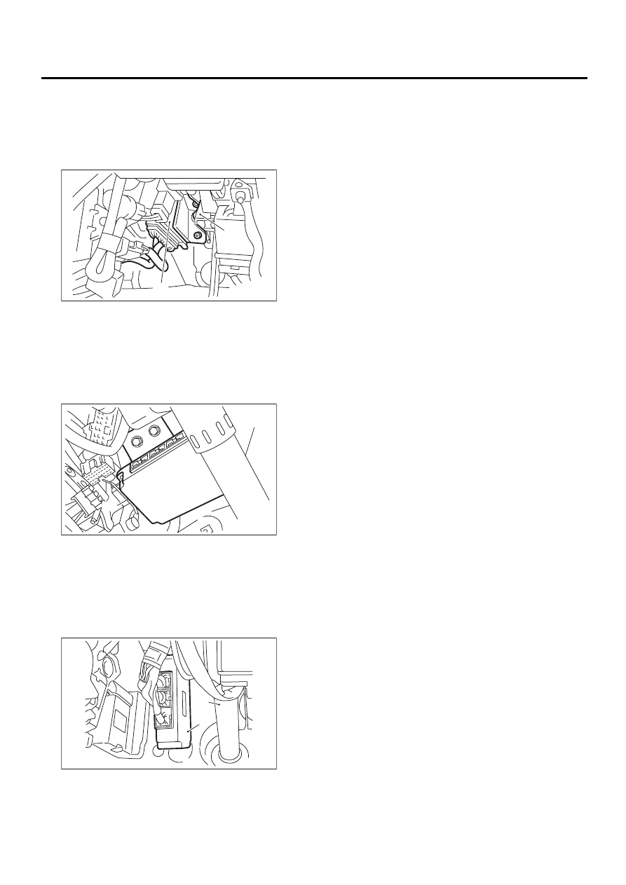
3) Disconnect the connectors from transmission
control module.
LHD model
RHD model except for Europe
RHD model for Europe
4) Remove the transmission control module.
(A) Transmission control module
(B) Brake pedal
(A) Transmission control module
(B) Column shaft
AT-00041
AT-00811
( A )
( B )
AT-00812
( A )
( B )
(A) Transmission control module
(B) Column shaft
AT-00802
( A )
( B )
AT-77
AUTOMATIC TRANSMISSION
TRANSMISSION CONTROL MODULE (TCM)
B: INSTALLATION
1) Install the transmission control module.
LHD model
Tightening torque:
7.5 N·m (0.76 kgf-m, 5.5 ft-lb)
RHD model except for Europe
Tightening torque:
7.5 N·m (0.76 kgf-m, 5.5 ft-lb)
RHD model for Europe
Tightening torque:
18 N·m (1.8 kgf-m, 13 ft-lb)
2) Connect the connectors to transmission control
module.
3) Install in the reverse order of removal.
(A) Transmission control module
(B) Brake pedal
(A) Transmission control module
(B) Column shaft
(A) Transmission control module
(B) Column shaft
AT-00811
( A )
( B )
AT-00813
( B )
( A )
AT-00802
( A )
( B )
Нет комментариевНе стесняйтесь поделиться с нами вашим ценным мнением.
Текст