Subaru Legacy III (2000-2003 year). Service manual — part 518
EN(H4DOSTC)-242
ENGINE (DIAGNOSTICS)
DIAGNOSTIC PROCEDURE WITH DIAGNOSTIC TROUBLE CODE (DTC)
BO:DTC P1711 — ENGINE TORQUE CONTROL SIGNAL #1 CIRCUIT MALFUNC-
TION —
• DTC DETECTING CONDITION:
• Two consecutive driving cycles with fault
• TROUBLE SYMPTOM:
• Excessive shift shock
CAUTION:
After repair or replacement of faulty parts, conduct Clear Memory Mode<Ref. to EN(H4DOSTC)-35,
OPERATION, Clear Memory Mode.> and Inspection Mode <Ref. to EN(H4DOSTC)-33, OPERATION, In-
spection Mode.> .
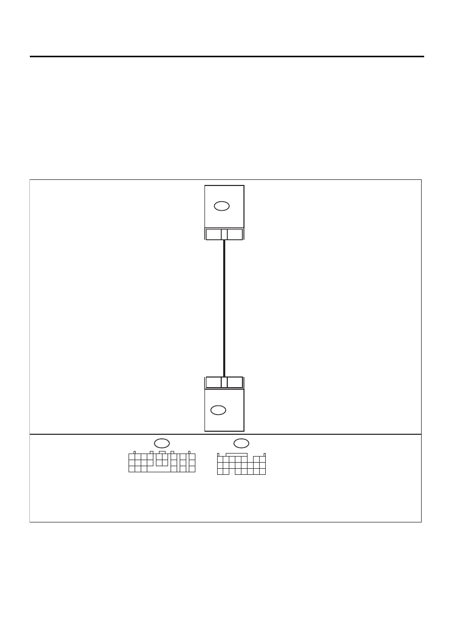
• WIRING DIAGRAM:
EN-01008
19
5
B134 ECM
TCM
B56
B134
B56
1 2
7
8
9
5 6
3 4
10 11 12
19 20 21
13
14 15
16
17
18
22
23
24
1 2 3 4
10 11 12
19 20 21
13
5
6
14 15
7
8 9
16 17
18
22

EN(H4DOSTC)-243
ENGINE (DIAGNOSTICS)
DIAGNOSTIC PROCEDURE WITH DIAGNOSTIC TROUBLE CODE (DTC)
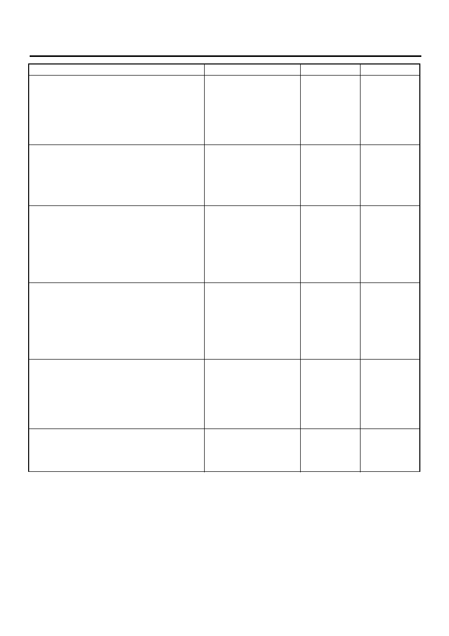
Step
Value
Yes
No
1
CHECK INPUT SIGNAL FOR ECM.
1) Turn ignition switch to ON.
2) Measure voltage between ECM and chas-
sis ground.
Connector & terminal
(B134) No. 19 (+) — Chassis ground (
−−−−
):
Does the measured value exceed the spec-
ified value?
4.5 V
2
CHECK INPUT SIGNAL FOR ECM.
Measure voltage between ECM and chassis
ground.
Connector & terminal
(B134) No. 19 (+) — Chassis ground (
−−−−
):
Does the measured value exceed the specified
value?
10 V
Repair battery
short circuit in har-
ness between
ECM and TCM
connector.
3
CHECK POOR CONTACT.
Check poor contact in ECM connector.
Is there poor contact in ECM connector?
There is poor contact.
Repair poor con-
tact in ECM con-
nector.
Contact SUBARU
distributor service.
NOTE:
Inspection by DTM
is required, be-
cause probable
cause is deteriora-
tion of multiple
parts.
4
CHECK HARNESS BETWEEN ECM AND
TCM CONNECTOR.
1) Turn ignition switch to OFF.
2) Disconnect connectors from ECM and
TCM.
3) Measure resistance of harness between
ECM and TCM connector.
Connector & terminal
(B134) No. 19 — (B56) No. 5:
Is the measured value less than the speci-
fied value?
1
Ω
Repair open circuit
in harness
between ECM and
TCM connector.
5
CHECK HARNESS BETWEEN ECM AND
TCM CONNECTOR.
Measure resistance of harness between ECM
and chassis ground.
Connector & terminal
(B134) No. 19 — Chassis ground:
Does the measured value exceed the specified
value?
1 M
Ω
Repair ground
short circuit in har-
ness between
ECM and TCM
connector.
6
CHECK POOR CONTACT.
Check poor contact in TCM connector.
Is there poor contact in TCM connector?
There is poor contact.
Repair poor con-
tact in TCM con-
nector.
Replace TCM.
<Ref. to AT-76,
Transmission Con-
trol Module
(TCM).>

EN(H4DOSTC)-244
ENGINE (DIAGNOSTICS)
DIAGNOSTIC PROCEDURE WITH DIAGNOSTIC TROUBLE CODE (DTC)
BP:DTC P1712 — ENGINE TORQUE CONTROL SIGNAL #2 CIRCUIT MALFUNC-
TION —
• DTC DETECTING CONDITION:
• Two consecutive driving cycles with fault
• TROUBLE SYMPTOM:
• Excessive shift shock
CAUTION:
After repair or replacement of faulty parts, conduct Clear Memory Mode<Ref. to EN(H4DOSTC)-35,
OPERATION, Clear Memory Mode.> and Inspection Mode <Ref. to EN(H4DOSTC)-33, OPERATION, In-
spection Mode.> .
• WIRING DIAGRAM:
EN-01009
18
14
B134 ECM
TCM
B56
B134
B56
1 2
7
8
9
5 6
3 4
10 11 12
19 20 21
13
14 15
16
17
18
22
23
24
1 2 3 4
10 11 12
19 20 21
13
5
6
14 15
7
8 9
16 17
18
22
EN(H4DOSTC)-245
ENGINE (DIAGNOSTICS)
DIAGNOSTIC PROCEDURE WITH DIAGNOSTIC TROUBLE CODE (DTC)
Step
Value
Yes
No
1
CHECK INPUT SIGNAL FOR ECM.
1) Turn ignition switch to ON.
2) Measure voltage between ECM and chas-
sis ground.
Connector & terminal
(B134) No. 18 (+) — Chassis ground (
−−−−
):
Does the measured value exceed the spec-
ified value?
4.5 V
2
CHECK INPUT SIGNAL FOR ECM.
Measure voltage between ECM and chassis
ground.
Connector & terminal
(B134) No. 18 (+) — Chassis ground (
−−−−
):
Does the measured value exceed the specified
value?
10 V
Repair battery
short circuit in har-
ness between
ECM and TCM
connector.
3
CHECK POOR CONTACT.
Check poor contact in ECM connector.
Is there poor contact in ECM connector?
There is poor contact.
Repair poor con-
tact in ECM con-
nector.
Contact SUBARU
distributor service.
NOTE:
Inspection by DTM
is required, be-
cause probable
cause is deteriora-
tion of multiple
parts.
4
CHECK HARNESS BETWEEN ECM AND
TCM CONNECTOR.
1) Turn ignition switch to OFF.
2) Disconnect connectors from ECM and
TCM.
3) Measure resistance of harness between
ECM and TCM connector.
Connector & terminal
(B134) No. 18 — (B56) No. 14:
1
Ω
Repair open circuit
in harness
between ECM and
TCM connector.
5
CHECK HARNESS BETWEEN ECM AND
TCM CONNECTOR.
Measure resistance of harness between ECM
and chassis ground.
Connector & terminal
(B134) No. 18 — Chassis ground:
Is the measured value less than the specified
value?
10
Ω
Repair ground
short circuit in har-
ness between
ECM and TCM
connector.
6
CHECK POOR CONTACT.
Check poor contact in TCM connector.
Is there poor contact in TCM connector?
There is poor contact.
Repair poor con-
tact in TCM con-
nector.
Replace TCM.
<Ref. to AT-76,
Transmission Con-
trol Module
(TCM).>
Нет комментариевНе стесняйтесь поделиться с нами вашим ценным мнением.
Текст