Subaru Legacy III (2000-2003 year). Service manual — part 65
ME(H4SO)-72
MECHANICAL
CYLINDER BLOCK
B: INSTALLATION
NOTE:
Remove oil in the mating surface of bearing and
cylinder block before installation. Also apply a coat
of engine oil to crankshaft pins.
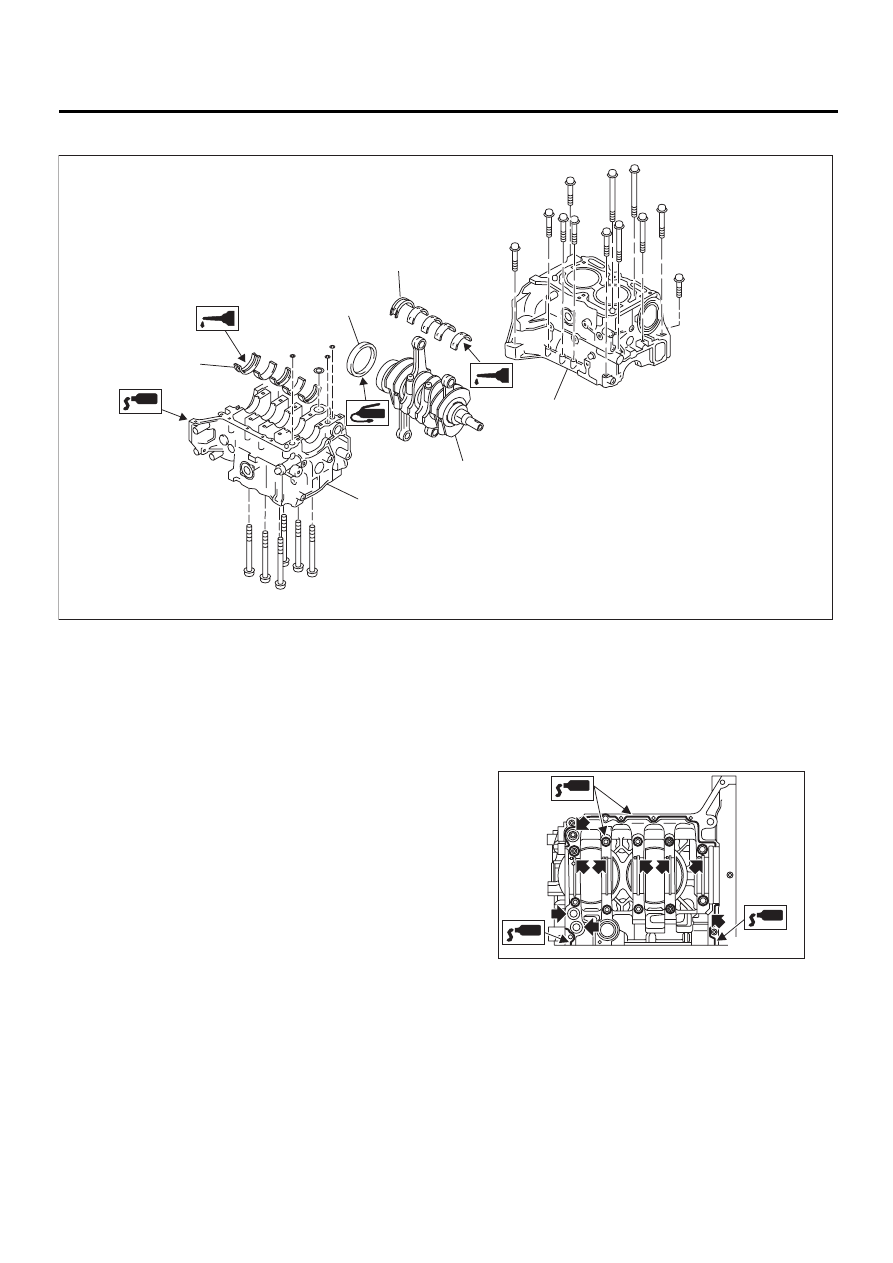
1) Position the crankshaft on #2 and #4 cylinder
block.
2) Apply fluid packing to the mating surface of #1
and #3 cylinder block, and position it on #2 and #4
cylinder block.
Fluid packing:
Part No. 004403007
THREE BOND 1215 or equivalent
NOTE:
Do not allow fluid packing to jut into O-ring grooves,
oil passages, bearing grooves, etc.
(1) Crankshaft bearing
(3) Cylinder block
(4) Rear oil seal
(2) Crankshaft
ME-00144
( 1 )
( 1 )
( 2 )
( 3 )
( 3 )
( 4 )
ME-00145
ME(H4SO)-73
MECHANICAL
CYLINDER BLOCK
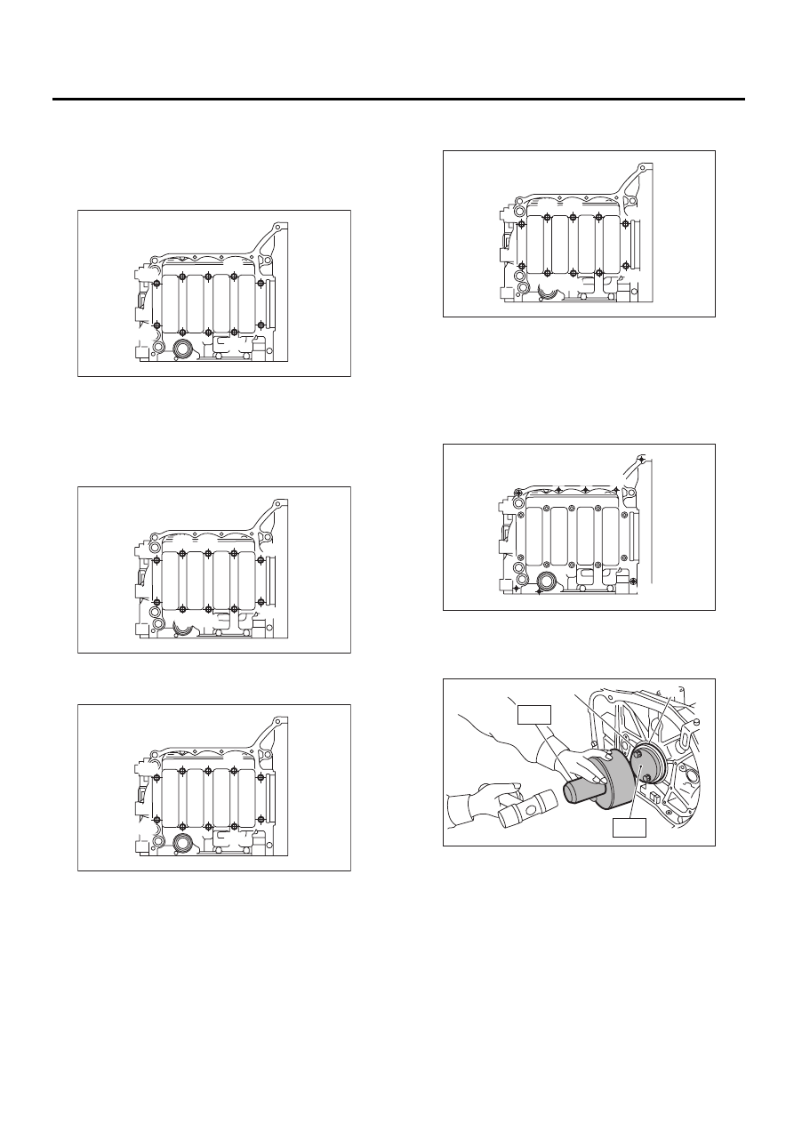
3) Tighten the 10 mm cylinder block connecting
bolts in alphabetical sequence shown in the figure.
(LH side)
Tightening torque:
15 N·m (1.5 kgf-m, 10.8 ft-lb)
4) Tighten the 10 mm cylinder block connecting
bolts in alphabetical sequence shown in the figure.
(RH side)
Tightening torque:
15 N·m (1.5 kgf-m, 10.8 ft-lb)
5) Further tighten the LH side bolts (A — D) to 90
°
in alphabetical sequence.
6) Further tighten the RH side bolts (E — J) to 90
°
in alphabetical sequence.
7) Tighten the 8 mm and 6 mm cylinder block con-
necting bolts in alphabetical sequence shown in the
figure.
Tightening torque:
(A) — (G): 25 N·m (2.5 kgf-m, 18.1 ft-lb)
(H): 6.4 N·m (0.65 kgf-m, 4.7 ft-lb)
8) Install the rear oil seal using ST1 and ST2.
ST1
499597100
OIL SEAL GUIDE
ST2
499587200
OIL SEAL INSTALLER
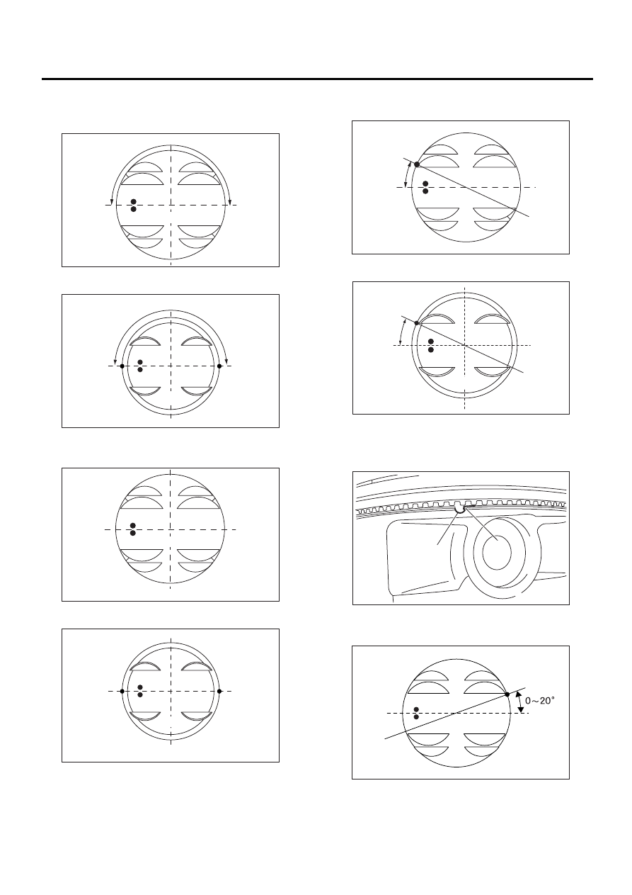
9) Position the top ring gap at (A) or (B) in the fig-
ure.
( A )
( B )
( C )
( D )
ME-00398
( F )
( E )
( I )
( G )
( H )
( J )
ME-00399
( A )
( B )
( C )
( D )
ME-00398
(A) Rear oil seal
(B) Flywheel attaching bolt
( F )
( E )
( I )
( G )
( H )
( J )
ME-00399
ME-00147
( A )
( B )
( C )
( D )
( E )
( F )
( G )
( H )
ME-00148
( A )
( B )
ST1
ST2
ME(H4SO)-74
MECHANICAL
CYLINDER BLOCK
10) Position the second ring gap at 180
°
on the re-
verse side for top ring gap.
• 2000 cc MODEL
• 2500 cc MODEL
11) Position the expander gap at (C) in the figure.
• 2000 cc MODEL
• 2500 cc MODEL
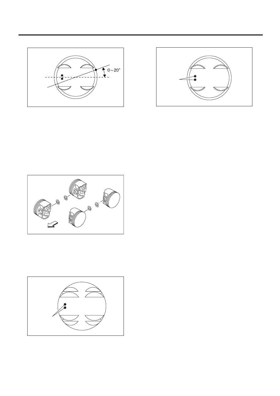
12) Position the lower rail gap at (D) in the figure.
• 2000 cc MODEL
• 2500 cc MODEL
NOTE:
Align the lower rail stopper (F) to the lateral hole (E)
on the piston.
13) Position the upper rail gap at (G) in the figure.
• 2000 cc MODEL
ME-00383
180˚
B0SH
( A )
( B )
ME-00691
5SH
180˚
( A )
( B )
ME-00384
B0SH
( C )
ME-00841
5SH
(C)
ME-00385
25˚
B0SH
( D )
ME-00402
25˚
5SH
( D )
ME-00304
( E )
( F )
(G)
B0SH
ME-00414
ME(H4SO)-75
MECHANICAL
CYLINDER BLOCK
• 2500 cc MODEL
NOTE:
• Ensure ring gaps do not face the same direction.
• Ensure ring gaps are not within the piston skirt
area.
14) Install circlip.
Install circlips in the piston holes located opposite
service holes in cylinder block, when positioning all
pistons in the corresponding cylinders.
NOTE:
Use new circlips.
CAUTION:
Piston front mark faces towards the front of the
engine.
• 2000 cc MODEL
• 2500 cc MODEL
(A) Front side
ME-00415
5SH
(G)
ME-00692
#1
#3
#4
#2
( A )
ME-00387
B0SH
( A )
(A) Front mark
ME-00404
5SH
( A )
Нет комментариевНе стесняйтесь поделиться с нами вашим ценным мнением.
Текст