Subaru Legacy III (2000-2003 year). Service manual — part 66
ME(H4SO)-76
MECHANICAL
CYLINDER BLOCK
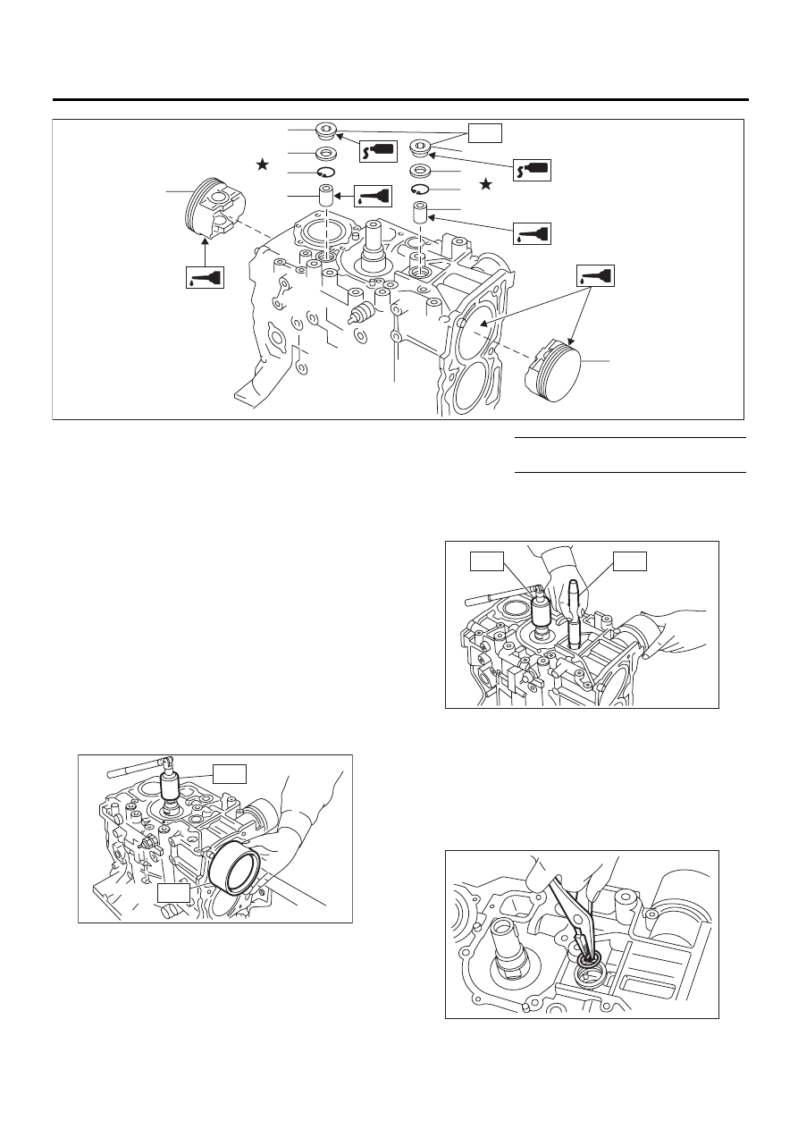
15) Installing piston
(1) Turn the cylinder block to face the #1 and #2
piston side upward.
(2) Using the ST1, turn the crankshaft so that
#1 and #2 connecting rods are set at bottom
dead center.
ST1
499987500
CRANKSHAFT SOCKET
(3) Apply a coat of engine oil to pistons and cyl-
inders, and then insert the pistons in their cylin-
ders using ST2.
ST2
398744300
PISTON GUIDE (2000 cc
model)
ST2
498747300
PISTON GUIDE (2500 cc
model)
16) Installing piston pin
(1) Apply a coat of engine oil to the ST3 before
insertion.
(2) Insert the ST3 into service hole to align pis-
ton pin hole with connecting rod small end.
ST3
499017100
PISTON PIN GUIDE
(3) Apply a coat of engine oil to the piston pin,
and then insert the piston pin into piston and
connecting rod through service hole.
(4) Install the circlip.
NOTE:
Use new circlips.
ST3
499897200
PISTON SNAPRING PLIER
(1) Piston
(4) Gasket
Tightening torque: N·m (kgf-m, ft-lb)
(2) Piston pin
(5) Service hole plug
T: 70 (7.0, 50.6)
(3) Circlip
( 1 )
( 2 )
( 3 )
( 4 )
( 5 )
( 2 )
( 3 )
( 4 )
( 5 )
T
( 1 )
ME-00155
ME-00157
ST1
ST2
ME-00158
ST1
ST3
ME-00159
ME(H4SO)-77
MECHANICAL
CYLINDER BLOCK
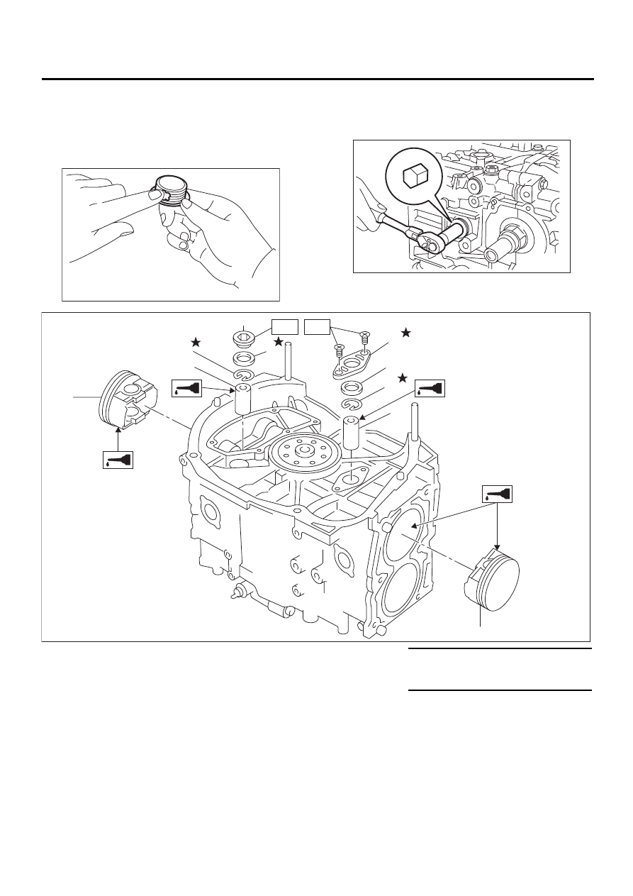
(5) Apply fluid packing around the service hole
plug.
Fluid packing:
Part No. 004403007
THREE BOND 1215 or equivalent
(6) Install the service hole plug and gasket.
NOTE:
Use a new gasket.
(7) Turn the cylinder block to face the #3 and #4
piston side upward. Using the same procedures
as used for #1 and #2 cylinders, install the pis-
tons and piston pins.
ME-00160
ME-00140
(1) Piston
(5) Service hole plug
Tightening torque: N·m (kgf-m, ft-lb)
(2) Piston pin
(6) Service hole cover
T1: 6.4 (0.65, 4.7)
(3) Circlip
(7) O-ring
T2: 70 (7.1, 51.4)
(4) Gasket
( 1 )
( 1 )
ME-00161
( 3 )
( 2 )
( 5 )
( 4 )
( 6 )
( 7 )
( 2 )
( 3 )
T2
T1
ME(H4SO)-78
MECHANICAL
CYLINDER BLOCK
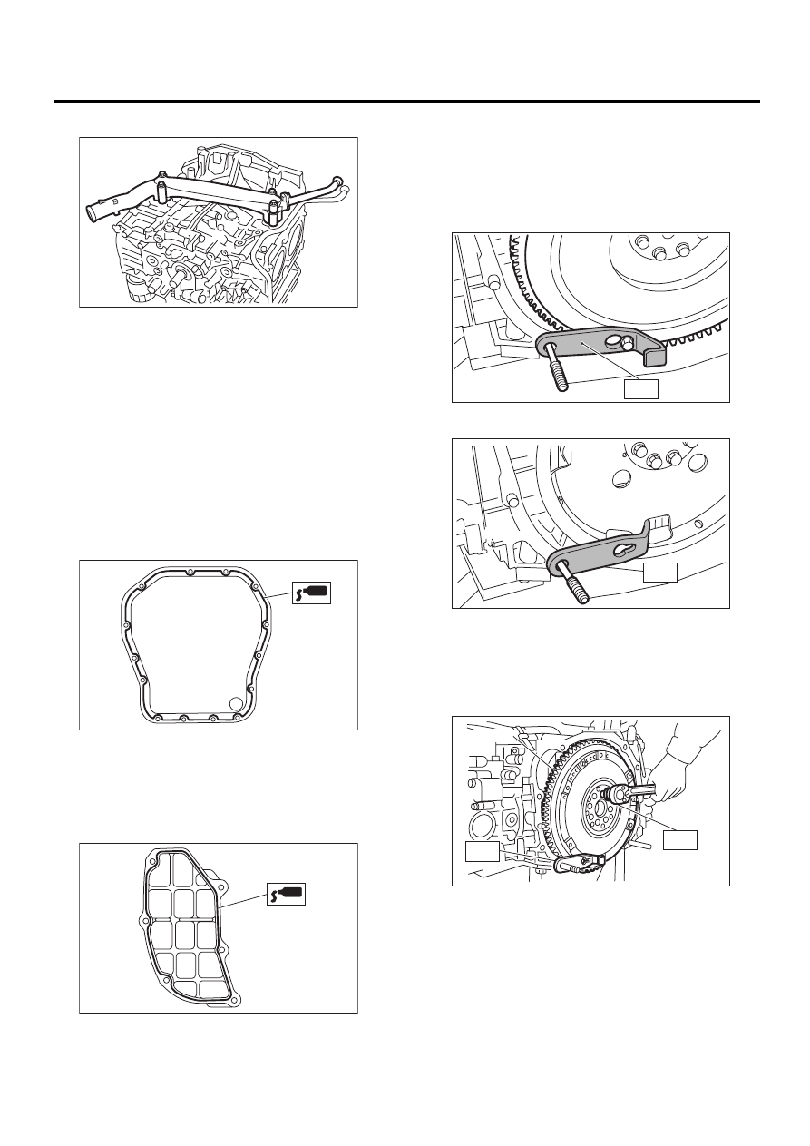
17) Install the water pipe.
18) Install the baffle plate.
Tightening torque:
6.4 N·m (0.65 kgf-m, 4.7 ft-lb)
19) Install the oil strainer and O-ring.
Tightening torque:
10 N·m (1.0 kgf-m, 7 ft-lb)
20) Install the oil strainer stay.
21) Apply fluid packing to the matching surfaces,
and then install the oil pan.
Fluid packing:
Part No. 004403007
THREE BOND 1215 or equivalent
22) Apply fluid packing to the matching surfaces,
and then install the oil separator cover.
Fluid packing:
Part No. 004403007
THREE BOND 1215 or equivalent
23) Install the flywheel or drive plate.
To lock the crankshaft, use ST.
ST
498497100
CRANKSHAFT STOPPER
Tightening torque:
72 N·m (7.3 kgf-m, 52.8 ft-lb)
• MT VEHICLES
• AT VEHICLES
NOTE:
Using STs, remove the flywheel. (2500 cc MT mod-
el)
ST1
498497100
CRANKSHAFT STOPPER
ST2
499057000
TORX PLUS
24) Install the housing cover.
ME-00300
ME-00162
ME-00163
(A) Flywheel
ME-00297
ST
ME-00298
ST
ME-00382
ST1
ST2
( A )
ME(H4SO)-79
MECHANICAL
CYLINDER BLOCK
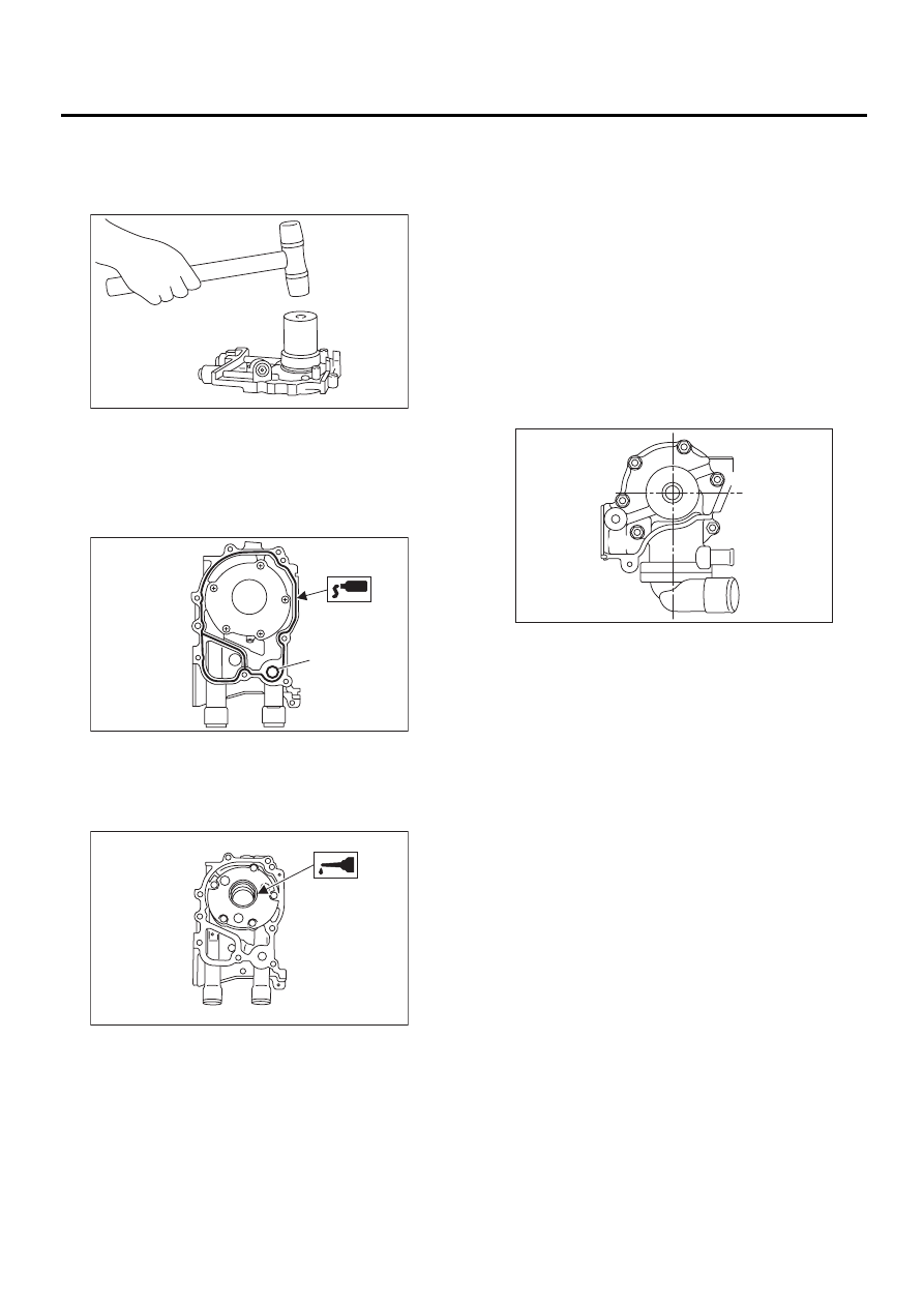
25) Installation of oil pump
(1) Discard the front oil seal after removal. Re-
place with a new one using the ST.
ST
499587100
OIL SEAL INSTALLER
(2) Apply fluid packing to the matching surface
of oil pump.
Fluid packing:
Part No. 004403007
THREE BOND 1215 or equivalent
(3) Apply a coat of engine oil to the inside of oil
seal.
(4) Install the oil pump on cylinder block. Be
careful not to damage the oil seal during instal-
lation.
Tightening torque:
6.4 N·m (0.65 kgf-m, 4.7 ft-lb)
NOTE:
• Do not forget to install the O-ring and seal when
installing oil pump.
• Align flat surface of oil pump's inner rotor with
crankshaft before installation.
26) Install the water pump and gasket.
Tightening torque:
First; 12 N·m (1.2 kgf-m, 8.7 ft-lb)
Second; 12 N·m (1.2 kgf-m, 8.7 ft-lb)
NOTE:
• Be sure to use a new gasket.
• When installing the water pump, tighten the bolts
in two stages in alphabetical sequence as shown in
the figure.
27) Install the water by-pass pipe for heater.
28) Install the oil filter using ST.
ST
498547000
OIL FILTER WRENCH
29) Tighten the cylinder head bolts.
(1) Apply a coat of engine oil to the washers and
bolt threads.
(2) Tighten all bolts to 29 N·m (3.0 kgf-m, 22 ft-
lb) in alphabetical sequence.
Then tighten all bolts to 69 N·m (7.0 kgf-m, 51 ft-
lb) in alphabetical sequence.
(3) Back off all bolts by 180
°
first; back them off
by 180
°
again.
(4) Tighten the bolts (a) and (b) to 34 N·m (3.5
kgf-m, 25 ft-lb).
(5) Tighten the bolts (c), (d), (e) and (f) to 15
N·m (1.5 kgf-m, 11 ft-lb).
(6) Tighten all bolts by 80 to 90
°
in alphabetical
sequence.
NOTE:
Do not tighten bolts more than 90
°
.
(7) Further tighten all bolts by 80 to 90
°
in al-
phabetical sequence.
(A) O-ring
ME-00164
( A )
ME-00165
ME-00312
ME-00333
( A )
( B )
( C )
( D )
( E )
( F )
Нет комментариевНе стесняйтесь поделиться с нами вашим ценным мнением.
Текст