Subaru Legacy III (2000-2003 year). Service manual — part 291
SP(H6DO)-4
SPEED CONTROL SYSTEMS
ACCELERATOR PEDAL
2. Accelerator Pedal
A: REMOVAL
1) Disconnect ground cable from battery.
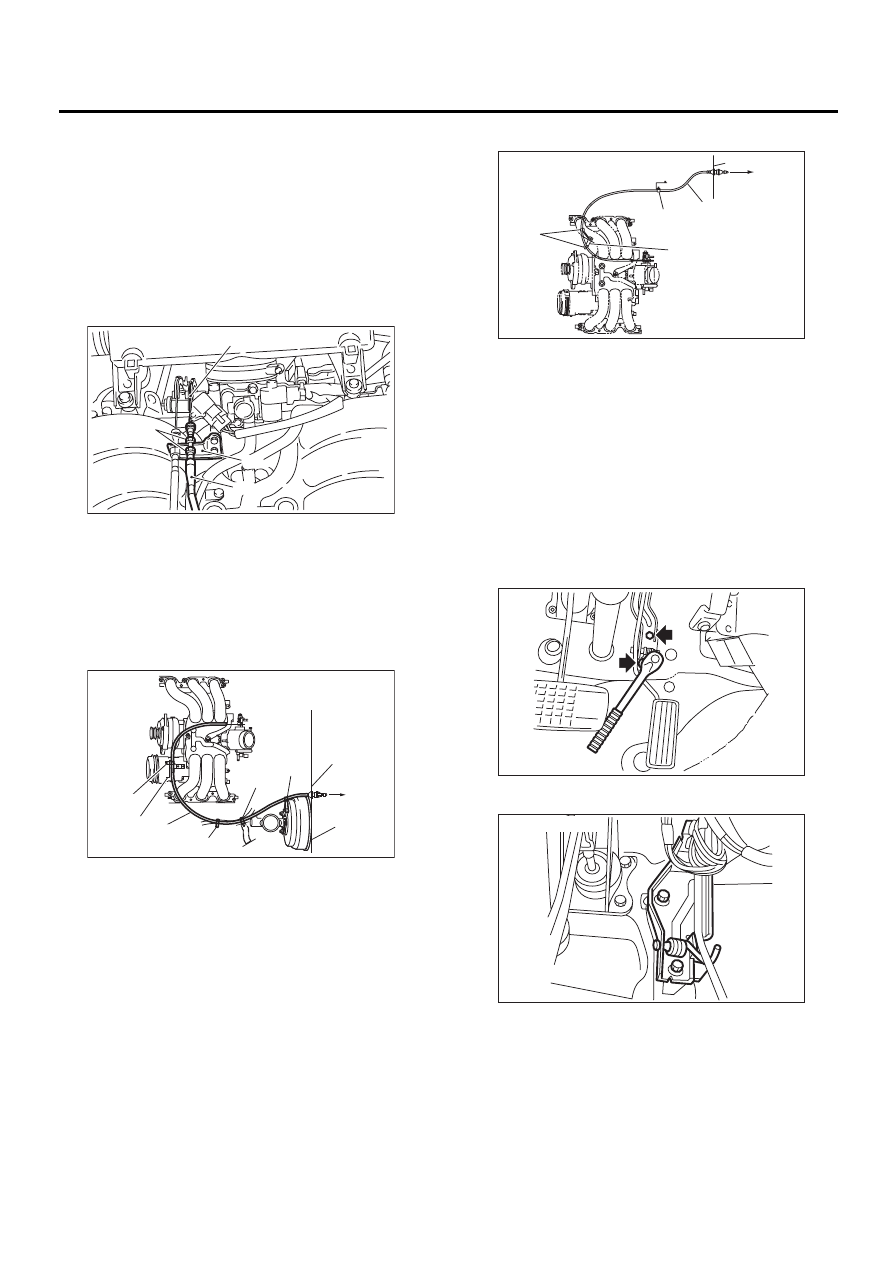
2) Remove lock nut from accelerator cable bracket.
3) Separate accelerator cable from bracket.
4) Remove accelerator cable end from throttle
cam.
NOTE:
Be careful not to kink accelerator cable.
5) Remove clip inside engine compartment.
• LHD MODEL
• RHD MODEL
6) Remove instrument panel lower cover from in-
strument panel, and connector.
7) Disconnect connector from kick-down switch.
8) Remove accelerator pedal connecting bolt from
accelerator pedal bracket.
• LHD MODEL
• RHD MODEL
(A) Lock nut
(B) Accelerator cable bracket
(C) Accelerator cable
(D) Throttle cam
(A) Toe board
(B) Accelerator cable
(C) To accelerator pedal
(D) Clip
(E) Bracket
(F) Brake booster
SP-00032
( A )
( B )
( C )
( D )
SP-00033
( A )
( B )
( C )
( D )
( D )
( D )
( D )
( E )
( F )
(A) Toe board
(B) Accelerator cable
(C) To accelerator pedal
(D) Clip
(E) Bracket
SP-00044
( A )
( B )
( C )
( D )
( D )
( E )
SP-00034
SP-00007
SP(H6DO)-5
SPEED CONTROL SYSTEMS
ACCELERATOR PEDAL
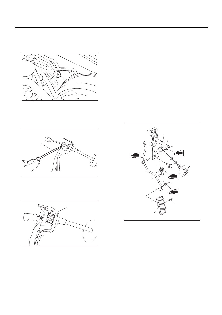
9) Disconnect grommet from toe board.
NOTE:
From engine compartment, push grommet into
hole.
10) Pull out the cable from the toe board hole.
11) Disconnect accelerator cable bushing from ac-
celerator pedal lever.
12) Disconnect accelerator cable stopper from
bracket.
13) Separate accelerator cable and bracket.
B: INSTALLATION
1) Install in the reverse order of removal.
NOTE:
• If cable clamp is damaged, replace it with a new
one.
• Never fail to cover outer cable end with boot.
• Be careful not to kink accelerator cable.
• Refer to COMPONENT for the tightening torque.
<Ref. to SP(H6DO)-2, COMPONENT, General De-
scription.>
2) Adjust the pedal after installation.
SP(H6DO)-7, ADJUSTMENT, Accelerator Pedal.>
C: DISASSEMBLY
1) Remove the clip, and then remove the accelera-
tor pedal from the bracket.
2) Pull out the spring pin, and then remove the ac-
celerator pedal from the accelerator pedal lever.
• LHD MODEL
(A) Grommet
(A) Slot-type screwdriver
(A) Accelerator cable stopper
( A )
SP-00035
( A )
SP-00036
( A )
SP-00037
(A) Accelerator bracket
(B) Stopper
(C) Bushing
(D) Clip
(E) Accelerator spring
(F) Accelerator pedal spring
(G) Accelerator pedal lever
(H) Spring pin
(I) Accelerator pedal
(J) Kick-down switch
SP-00024
( A )
( B )
( C )
( D )
( E )
( F )
( G )
( H )
( I )
( J )
SP(H6DO)-6
SPEED CONTROL SYSTEMS
ACCELERATOR PEDAL
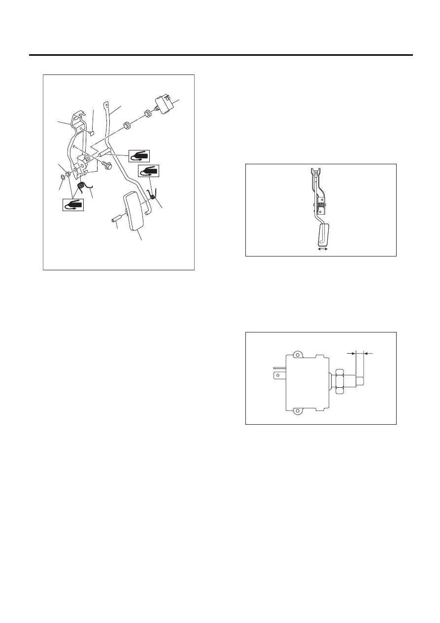
• RHD MODEL
D: ASSEMBLY
Assemble in the reverse order of disassembly.
NOTE:
Clean and apply grease to the position as shown in
the figure.
Grease:
Part No. 003602010
SUNLIGHT No. 2
E: INSPECTION
1. ACCELERATOR PEDAL
1) Lightly move pedal pad in the lateral direction to
ensure pedal deflection is in specified range.
2) If excessive deflection is noted, replace bushing
and clip with new ones.
Deflection of accelerator pedal:
Service limit
±2.0 mm (±0.079 in) or less
2. KICK-DOWN SWITCH
If kick-down switch does not operate properly (or if
it does not stop at the specified position), replace
with a new one.
Specified position: A
2.0 — 3.5 mm (0.079 — 0.138 in)
(A) Accelerator bracket
(B) Stopper
(C) Bushing
(D) Clip
(E) Accelerator spring
(F) Accelerator pedal spring
(G) Accelerator pedal lever
(H) Spring pin
(I) Accelerator pedal
(J) Kick-down switch
SP-00025
( A )
( B )
( C )
( D )
( E )
( F )
( G )
( J )
( I )
( H )
SP-00039
SP-00026
A
SP(H6DO)-7
SPEED CONTROL SYSTEMS
ACCELERATOR PEDAL
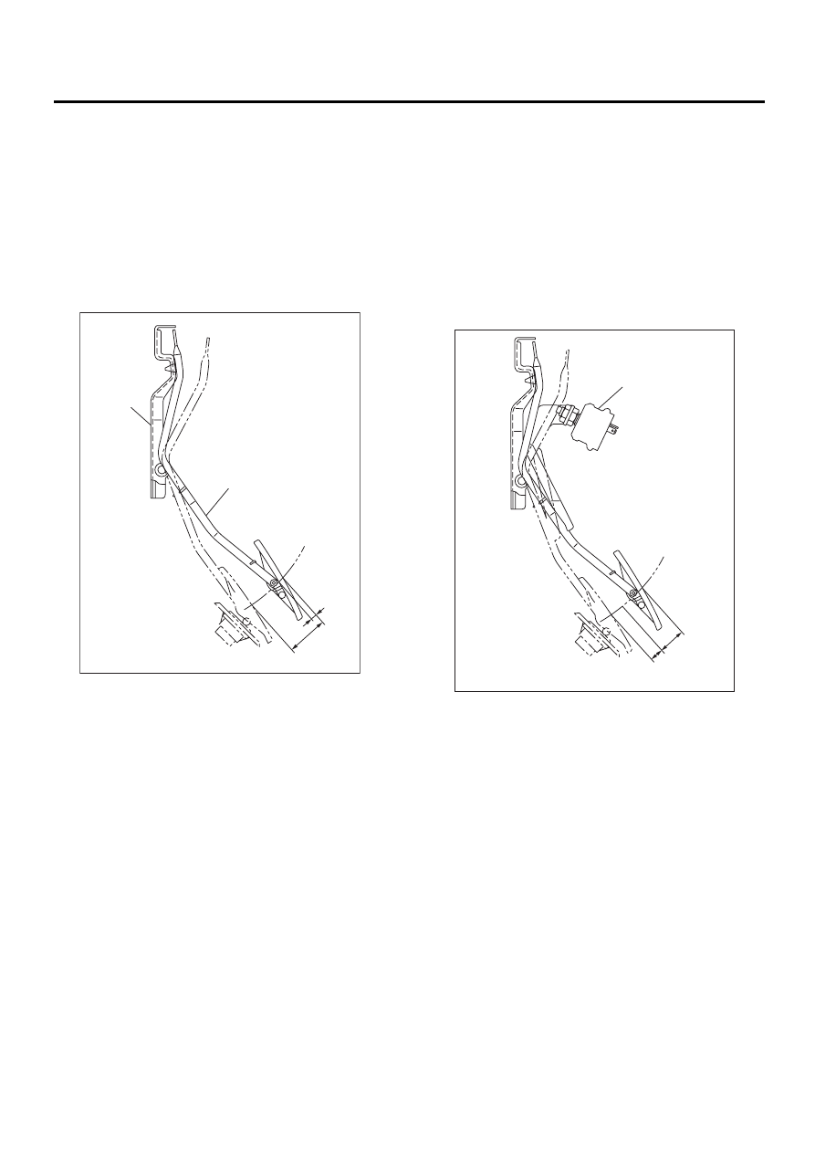
F: ADJUSTMENT
1) Check pedal stroke and free play by operating
accelerator pedal by hand.
2) If it is not within specified value, adjust it by turn-
ing nut connecting accelerator cable to throttle
body.
Free play at pedal pad: L
0 — 4 mm (0 — 0.16 in)
Stroke at pedal pad: A
50 — 55 mm (1.97 — 2.17 in)
Tightening torque of accelerator cable lock nut:
12 N·m (1.2 kgf-m, 9 ft-lb)
3) Check to ensure the kick-down switch operates
at the specified value in relation to the stroke of the
accelerator pedal.
If it is not in specified value, adjust it by adjusting
position of kick-down switch.
NOTE:
Be careful not to rotate kick-down switch.
Kick-down switch stroke: A
47 — 49 mm (1.85 — 1.93 in)
Kick-down switch tightening torque:
12 N·m (1.2 kgf-m, 8.7 ft-lb)
(A) Accelerator pedal
(B) Accelerator pedal bracket
SP-00040
A
L
( A )
( B )
(A) Kick-down switch
SP-00028
L
OFF
ON
( A )
Нет комментариевНе стесняйтесь поделиться с нами вашим ценным мнением.
Текст