Subaru Legacy III (2000-2003 year). Service manual — part 263
ME(H6DO)-40
MECHANICAL
FRONT CHAIN COVER
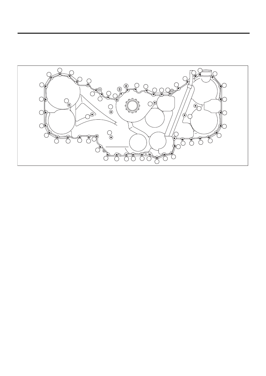
4) Tighten the bolts in the numerical sequence
shown in figure.
Tightening torque:
6.6 N·m (0.67 kgf-m, 4.8 ft-lb)
5) Install crankshaft pulley. <Ref. to ME(H6DO)-38,
INSTALLATION, Crankshaft Pulley.>
C: INSPECTION
Check the cover surface for flaws and dents.
Check the cover mating surface and the mounting
point of crankshaft pulley for oil leaks.
ME-00500
1
2
3
5
6
4
7
10
26
25
24
23
22
21
20
19
27
28
29
30
31
32
59
58
57
56
55
54
53
52
51
50
49
48
47
46
45
44
43
42
41
40
39
38
37
36
35
34
33
18
17
16
15
14
13
12
11
ME(H6DO)-41
MECHANICAL
TIMING CHAIN ASSEMBLY
12.Timing Chain Assembly
A: REMOVAL
1) Remove crankshaft pulley. <Ref. to ME(H6DO)-
38, REMOVAL, Crankshaft Pulley.>
2) Remove front chain cover. <Ref. to ME(H6DO)-
39, REMOVAL, Front Chain Cover.>
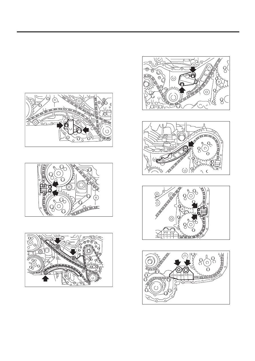
3) Remove chain tensioner (RH).
NOTE:
Make sure plunger (A) does not come out.
4) Remove chain guide. (Right-hand between
cams)
5) Remove chain guide (RH).
6) Remove chain tensioner lever (RH).
7) Remove timing chain (RH).
8) Remove chain tensioner (LH).
NOTE:
Make sure plunger (A) does not come out.
9) Remove chain tensioner lever (LH).
Remove chain guide. (Left-hand between cams)
10) Remove chain guide (LH).
(A) Chain guide (RH)
(B) Chain tensioner lever (RH)
ME-00501
( A )
ME-00502
ME-00503
( A )
( B )
ME-00504
( A )
ME-00505
ME-00506
ME-00507
ME(H6DO)-42
MECHANICAL
TIMING CHAIN ASSEMBLY
11) Remove chain guide. (Center)
12) Remove idler sprocket. (Upper)
13) Remove timing chain (LH).
14) Remove idler sprocket. (Lower)
B: INSTALLATION
NOTE:
• During installation, be careful to prevent foreign
objects from attaching to or mixing with assembled
components.
• Apply engine oil to chain guide, chain tensioner
lever, and idler sprocket during installation.
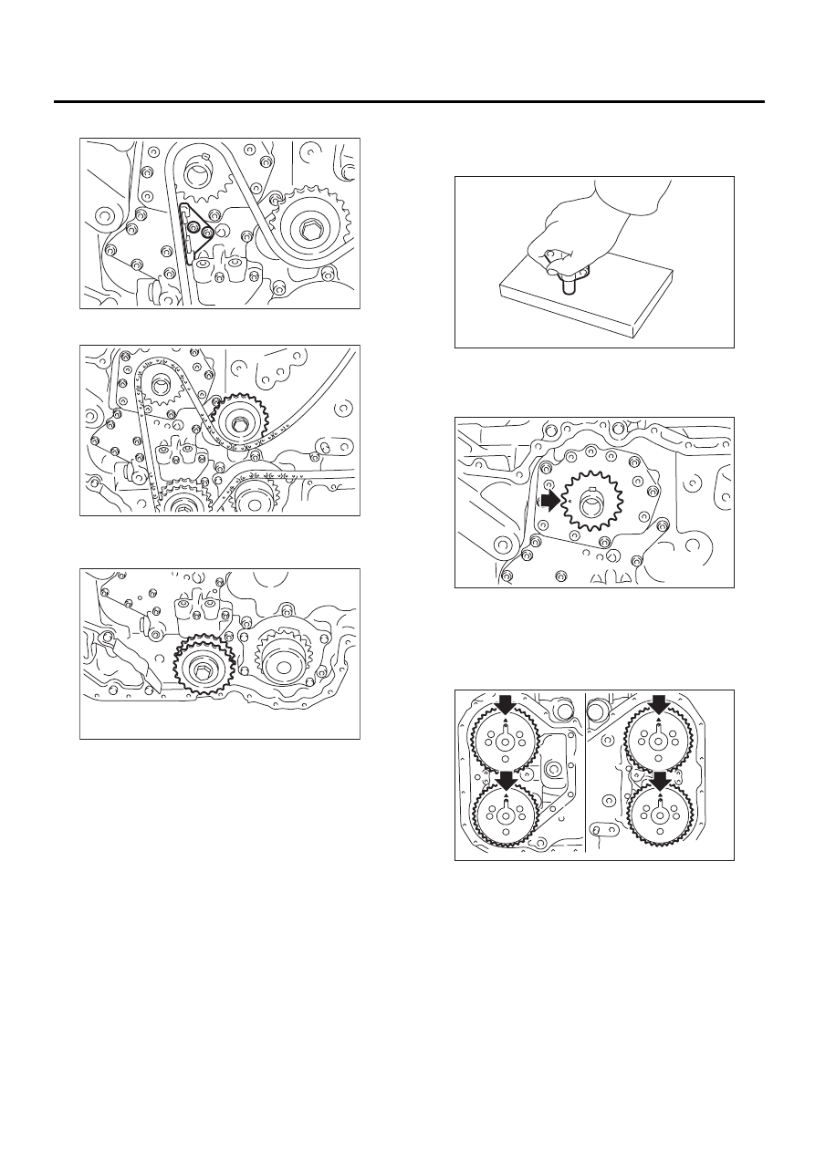
1) Preparation for installation of chain tensioner.
(1) Put the screw, spring, pin and tension rod
into the tensioner body.
(2) While pressing tensioner onto rubber mat,
twist it left and right to shorten tension rod. Then
set a thin pin into the holes between tension rod
and tensioner body to hold it.
NOTE:
Carry out the work on rubber mat or other nonslip
material.
2) Using ST, align “top mark” on crankshaft sprock-
et at 9 o'clock position as shown in the figure.
ST
18252AA000
CRANKSHAFT SOCKET
3) Using ST, align four key grooves on camshaft
sprocket at 12 o'clock position as shown in the fig-
ure.
ST
18231AA000
CAMSHAFT SPROCKET
WRENCH
ME-00508
ME-00509
ME-00510
ME-00511
ME-00512
ME-00513
ME(H6DO)-43
MECHANICAL
TIMING CHAIN ASSEMBLY
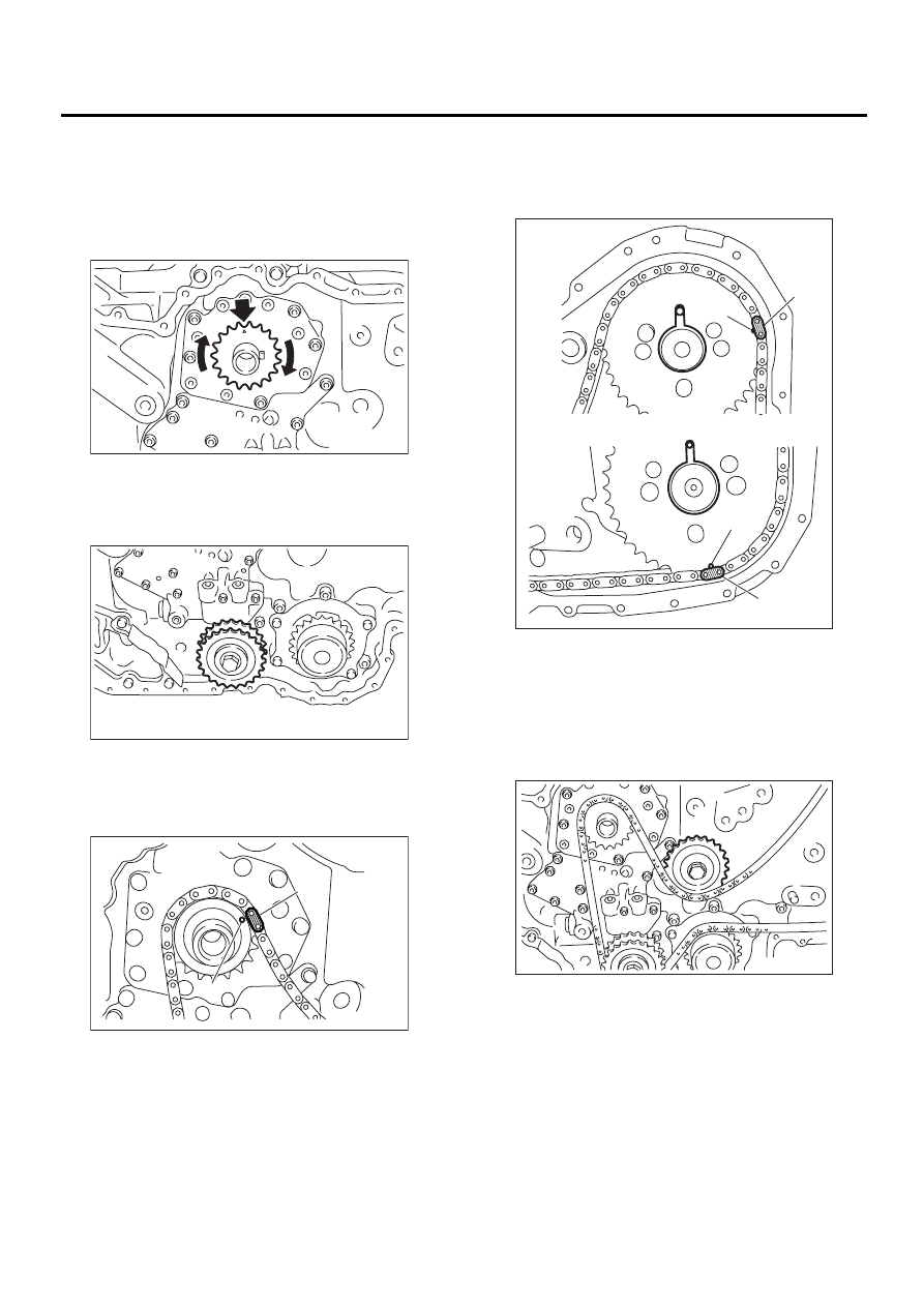
4) Rotate crankshaft sprocket clockwise to align
“top mark” at 12 o'clock position as shown in the fig-
ure. (Piston # 1 is at TDC.)
NOTE:
Do not rotate crankshaft and camshaft sprockets
until timing chain is completely routed.
5) Install the idler sprocket. (Lower)
Tightening torque:
69 N·m (7.0 kgf-m, 50.6 ft-lb)
6) Install timing chain LH.
(1) Align the timing mark (B) on crankshaft
sprocket with the matching mark (A) on timing
chain LH.
(2) Route timing chain LH on idler sprocket
(Lower), water pump, exhaust cam sprocket,
and intake cam sprocket in order.
NOTE:
Make sure that matching marks on the timing chain
(A) and camshaft sprocket (B) are aligned the
same way as the one on crankshaft sprocket.
(3) Install chain idler. (Upper)
Tightening torque:
69 N·m (7.0 kgf-m, 50.6 ft-lb)
(A) Gold
(B) Mark
ME-00514
ME-00510
ME-00515
( A )
( B )
(A) Dark blue
(B) Mark
ME-00516
( A )
( B )
( A )
( B )
ME-00509
Нет комментариевНе стесняйтесь поделиться с нами вашим ценным мнением.
Текст