Subaru Legacy III (2000-2003 year). Service manual — part 585

AT-74
AUTOMATIC TRANSMISSION (DIAGNOSTICS)
DIAGNOSTIC PROCEDURE WITH DIAGNOSTIC TROUBLE CODE (DTC)
7
CHECK SHIFT SOLENOID 1 (IN TRANSMIS-
SION).
1) Remove transmission connector from
bracket.
2) Lift-up or raise the vehicle and support with
safety stand.
3) Drain automatic transmission fluid.
CAUTION:
Do not drain the automatic transmission flu-
id until it cools down.
4) Remove oil pan, and disconnect connector
from shift solenoid 1.
5) Measure resistance between shift solenoid
1 connector and transmission ground.
Terminal
No. 1 — Transmission ground:
Is the measured value within the specified
range?
10 — 16
Ω
Replace shift sole-
noid 1. <Ref. to
AT-67, Shift Sole-
noids, Duty Sole-
noids and ATF
Temperature Sen-
sor.>
8
CHECK HARNESS CONNECTOR BETWEEN
SHIFT SOLENOID 1 AND TRANSMISSION.
Measure resistance of harness between shift
solenoid 1 and transmission connector.
Connector & terminal
(AT5) No. 1 — (T4) No. 1:
Is the measured value less than the specified
value?
1
Ω
Repair open circuit
in harness
between shift sole-
noid 1 and trans-
mission connector.
9
CHECK HARNESS CONNECTOR BETWEEN
SHIFT SOLENOID 1 AND TRANSMISSION.
Measure resistance of harness between shift
solenoid 1 connector and transmission ground.
Connector & terminal
(T4) No. 1 — Transmission ground:
Does the measured value exceed the specified
value?
1 M
Ω
Even if “POWER”
indicator lights up,
the circuit has
returned to a nor-
mal condition at
this time. A tempo-
rary poor contact
of the connector or
harness may be
the cause. Repair
harness or con-
nector in shift sole-
noid 1 and
transmission.
Repair short circuit
harness between
shift solenoid 1
and transmission
connector.
Step
Value
Yes
No
AT-75
AUTOMATIC TRANSMISSION (DIAGNOSTICS)
DIAGNOSTIC PROCEDURE WITH DIAGNOSTIC TROUBLE CODE (DTC)
MEMO:
AT-76
AUTOMATIC TRANSMISSION (DIAGNOSTICS)
DIAGNOSTIC PROCEDURE WITH DIAGNOSTIC TROUBLE CODE (DTC)
J: DTC 72 SHIFT SOLENOID 2
DIAGNOSIS:
Output signal circuit of shift solenoid 2 is open or shorted.
TROUBLE SYMPTOM:
Does not shift.
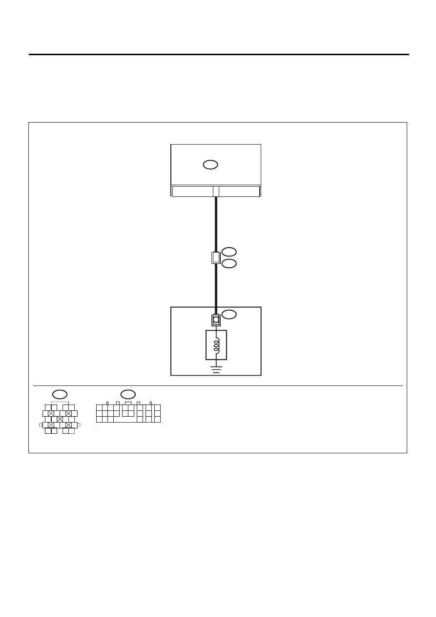
WIRING DIAGRAM:
AT-00584
5
TRANSMISSION
B54
TCM
AT6
SHIFT
SOLENOID 2
B54
1 2
7
8
9
5 6
3 4
10 11 12
19 20 21
13
14 15
16
17
18
22
23
24
T4
B11
2
B11
1 2
5
6 7
8
13
14 15
16
9 10
11 12
3 4
17 18
19 20

AT-77
AUTOMATIC TRANSMISSION (DIAGNOSTICS)
DIAGNOSTIC PROCEDURE WITH DIAGNOSTIC TROUBLE CODE (DTC)
Step
Value
Yes
No
1
CHECK HARNESS CONNECTOR BETWEEN
TCM AND TRANSMISSION.
1) Turn ignition switch to OFF.
2) Disconnect connector from TCM and trans-
mission.
3) Measure resistance of harness between
TCM and shift solenoid 2 connector.
Connector & terminal
(B54) No. 5 — (B11) No. 2:
Is the measured value less than the speci-
fied value?
1
Ω
Repair open circuit
in harness
between TCM and
transmission con-
nector.
2
CHECK HARNESS CONNECTOR BETWEEN
TCM AND TRANSMISSION.
Measure resistance of harness between TCM
connector and transmission ground.
Connector & terminal
(B54) No. 5 — Transmission ground:
Does the measured value exceed the specified
range?
1 M
Ω
Repair short circuit
in harness
between TCM and
transmission con-
nector.
3
CHECK SHIFT SOLENOID 2.
Measure resistance between transmission
connector terminals.
Connector & terminal
(T4) No. 2 — No. 16:
Is the measured value within the specified
range?
10 — 16
Ω
4
CHECK OUTPUT SIGNAL EMITTED FROM
TCM.
1) Connect connectors to TCM and transmis-
sion.
2) Lift-up or raise the vehicle and support with
safety stand.
NOTE:
Raise all wheels off ground.
3) Start the engine and warm-up the transmis-
sion until ATF temperature is above 80
°
C
(176
°
F).
NOTE:
If ambient temperature is below 0
°
C (32
°
F),
drive the vehicle until the ATF reaches its oper-
ating temperature.
4) Move selector lever to “D”, and slowly
increase vehicle speed to 50 km/h (31
MPH).
NOTE:
The speed difference between front and rear
wheels may light the ABS warning light, but this
indicates no malfunction. When AT control di-
agnosis is finished, perform the ABS memory
clearance procedure of on-board diagnostics
system. <Ref. to ABS-22, Clear Memory
Mode.> or <Ref. to VDC-25, Clear Memory
Mode.>
5) Measure voltage between TCM connector
and chassis ground.
Connector & terminal
(B54) No. 22 (+) — Chassis ground (
−−−−
):
Is the measured value less than the speci-
fied value?
1 V
Even if “POWER”
indicator lights up,
the circuit has
returned to a nor-
mal condition at
this time. A tempo-
rary poor contact
of the connector or
harness may be
the cause. Repair
harness or con-
nector in the TCM
and transmission.
Нет комментариевНе стесняйтесь поделиться с нами вашим ценным мнением.
Текст