Subaru Legacy III (2000-2003 year). Service manual — part 586

AT-78
AUTOMATIC TRANSMISSION (DIAGNOSTICS)
DIAGNOSTIC PROCEDURE WITH DIAGNOSTIC TROUBLE CODE (DTC)
5
CHECK POOR CONTACT.
Is there poor contact in shift solenoid 2 circuit?
There is poor contact.
Repair poor con-
tact.
Replace TCM.
<Ref. to AT-76,
Transmission Con-
trol Module
(TCM).>
6
CHECK SHIFT SOLENOID 2 (IN TRANSMIS-
SION).
1) Remove transmission connector from
bracket.
2) Drain automatic transmission fluid.
CAUTION:
Do not drain the automatic transmission flu-
id until it cools down.
3) Remove oil pan, and disconnect connector
from shift solenoid 2.
4) Measure resistance between shift solenoid
2 connector and transmission ground.
Connector & terminal
No. 1 — Transmission ground:
Is the measured value within the specified
range?
10 — 16
Ω
Replace shift sole-
noid 2 assembly.
<Ref. to AT-67,
Shift Solenoids,
Duty Solenoids
and ATF Temper-
ature Sensor.>
7
CHECK HARNESS CONNECTOR BETWEEN
SHIFT SOLENOID 2 AND TRANSMISSION.
Measure resistance of harness between shift
solenoid 2 and transmission connector.
Connector & terminal
(AT6) No. 1 — (T4) No. 2:
Is the measured value less than the specified
value?
1
Ω
Repair open circuit
in harness
between shift sole-
noid 2 and trans-
mission connector.
8
CHECK HARNESS CONNECTOR BETWEEN
SHIFT SOLENOID 2 AND TRANSMISSION.
Measure resistance of harness between shift
solenoid 2 connector and transmission ground.
Connector & terminal
(T4) No. 2 — Transmission ground:
Does the measured value exceed the specified
value?
1 M
Ω
Even if “POWER”
indicator lights up,
the circuit has
returned to a nor-
mal condition at
this time. A tempo-
rary poor contact
of the connector or
harness may be
the cause. Repair
harness or con-
nector in shift sole-
noid 2 and
transmission.
Repair short circuit
harness between
shift solenoid 2
and transmission
connector.
Step
Value
Yes
No
AT-79
AUTOMATIC TRANSMISSION (DIAGNOSTICS)
DIAGNOSTIC PROCEDURE WITH DIAGNOSTIC TROUBLE CODE (DTC)
MEMO:
AT-80
AUTOMATIC TRANSMISSION (DIAGNOSTICS)
DIAGNOSTIC PROCEDURE WITH DIAGNOSTIC TROUBLE CODE (DTC)
K: DTC 73 LOW CLUTCH TIMING SOLENOID
DIAGNOSIS:
Output signal circuit of low clutch timing solenoid is open or shorted.
TROUBLE SYMPTOM:
Excessive shift shock.
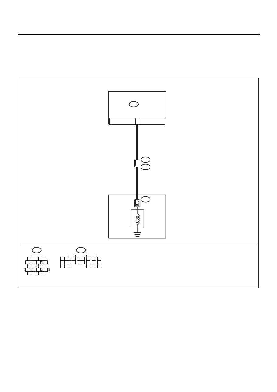
WIRING DIAGRAM:
AT-00585
15
TRANSMISSION
B54
TCM
AT 9
LOW CLUTCH
TIMING
SOLENOID
B54
1 2
7
8
9
5 6
3 4
10 11 12
19 20 21
13
14 15
16
17
18
22
23
24
T4
B11
3
B11
1 2
5
6 7
8
13
14 15
16
9 10
11 12
3 4
17 18
19 20

AT-81
AUTOMATIC TRANSMISSION (DIAGNOSTICS)
DIAGNOSTIC PROCEDURE WITH DIAGNOSTIC TROUBLE CODE (DTC)
Step
Value
Yes
No
1
CHECK HARNESS CONNECTOR BETWEEN
TCM AND TRANSMISSION.
1) Turn ignition switch to OFF.
2) Disconnect connector from TCM and trans-
mission.
3) Measure resistance of harness between
TCM and transmission connector.
Connector & terminal
(B54) No. 15 — (B11) No. 3:
Is the measured value less than the speci-
fied value?
1
Ω
Repair open circuit
in harness
between TCM and
transmission con-
nector.
2
CHECK HARNESS CONNECTOR BETWEEN
TCM AND TRANSMISSION.
Measure resistance of harness between TCM
connector and transmission ground.
Connector & terminal
(B54) No. 15 — Chassis ground:
Does the measured value exceed the specified
value?
1 M
Ω
Repair short circuit
in harness
between TCM and
transmission con-
nector.
3
CHECK LOW CLUTCH TIMING SOLENOID.
Measure resistance between transmission
connector terminals.
Connector & terminal
(T4) No. 3 — No. 16:
Is the measured value within the specified
range?
10 — 16
Ω
4
CHECK OUTPUT SIGNAL EMITTED FROM
TCM.
1) Connect connectors to TCM and transmis-
sion.
2) Turn ignition switch to ON (engine OFF).
3) Move select lever to “D” range.
4) Measure voltage between TCM connector
and chassis ground.
Connector & terminal
(B54) No. 15 (+) — Chassis ground (
−−−−
):
Does the measured value exceed the spec-
ified value?
9V
5
CHECK OUTPUT SIGNAL EMITTED FROM
TCM.
1) Hold switch to ON.
2) Measure voltage between TCM connector
and chassis ground.
Connector & terminal
(B54) No. 15 (+) — Chassis ground (
−−−−
):
Is the measured value less than the speci-
fied value?
1V
Even if “POWER”
indicator lights up,
the circuit has
returned to a nor-
mal condition at
this time. A tempo-
rary poor contact
of the connector or
harness may be
the cause. Repair
harness or con-
tact in the TCM
and transmission.
6
CHECK POOR CONTACT.
Is there poor contact in low clutch timing sole-
noid circuit?
There is poor contact.
Repair poor con-
tact.
Replace TCM.
<Ref. to AT-76,
Transmission Con-
trol Module
(TCM).>
Нет комментариевНе стесняйтесь поделиться с нами вашим ценным мнением.
Текст