Subaru Legacy III (2000-2003 year). Service manual — part 602
AT-142
AUTOMATIC TRANSMISSION (DIAGNOSTICS)
DIAGNOSTIC PROCEDURE FOR NO-DIAGNOSTIC TROUBLE CODE (DTC)
61
CHECK INPUT SIGNAL FOR TCM.
1) Position select lever to any other than 1
range.
2) Measure voltage between TCM and chas-
sis ground.
Connector & terminal
(B55) No. 7 (+) — Chassis ground (–):
Does the measured value exceed the spec-
ified value?
8 V
Replace TCM.
<Ref. to AT-76,
Transmission Con-
trol Module
(TCM).>
62
CHECK “1” RANGE INDICATOR LIGHT
BULB.
1) Turn ignition switch to OFF.
2) Remove combination meter.
3) Remove “1” range indicator light bulb from
combination meter.
Is “1” range indicator light bulb OK?
Bulb is normal.
Replace “1” range
indicator light bulb.
<Ref. to IDI-14,
Combination
Meter Assembly.>
63
CHECK HARNESS CONNECTOR BETWEEN
TCM AND COMBINATION METER.
1) Disconnect connectors from TCM and com-
bination meter.
2) Measure resistance of harness between
TCM and combination meter.
Connector & terminal
Except 3.0 L model and TURBO model:
(B55) No. 7 — (i11) No. 5:
3.0 L model and TURBO model:
(B55) No. 7 — (i10) No. 15:
Does the measured value exceed the spec-
ified value?
1
Ω
Repair open circuit
in harness
between TCM and
combination
meter, and poor
contact in TCM
connector.
64
CHECK HARNESS CONNECTOR BETWEEN
TCM AND INHIBITOR SWITCH.
1) Turn ignition switch to OFF.
2) Disconnect connectors from TCM, inhibitor
switch and combination meter.
3) Measure resistance of harness between
TCM and chassis ground.
Connector & terminal
(B55) No. 7 — Chassis ground:
Does the measured value exceed the spec-
ified value?
1 M
Ω
Repair ground
short circuit in “1”
range circuit.
65
CHECK POOR CONTACT.
Is there poor contact in inhibitor switch circuit?
There is poor contact.
Repair poor con-
tact.
Adjust inhibitor
switch and select
cable. <Ref. to AT-
50, ADJUST-
MENT, Inhibitor
Switch.> and
<Ref. to CS-12,
Select Cable.>
Step
Value
Yes
No
AT-143
AUTOMATIC TRANSMISSION (DIAGNOSTICS)
DIAGNOSTIC PROCEDURE FOR NO-DIAGNOSTIC TROUBLE CODE (DTC)
MEMO:
AT-144
AUTOMATIC TRANSMISSION (DIAGNOSTICS)
DIAGNOSTIC PROCEDURE FOR NO-DIAGNOSTIC TROUBLE CODE (DTC)
I:
CHECK HOLD SWITCH.
DIAGNOSIS:
• LED does not come on when hold switch is ON.
• Hold switch circuit is open or shorted.
TROUBLE SYMPTOM:
• 2nd gear is not held.
• Failure of vehicle to start in 2nd gear except 1st range.
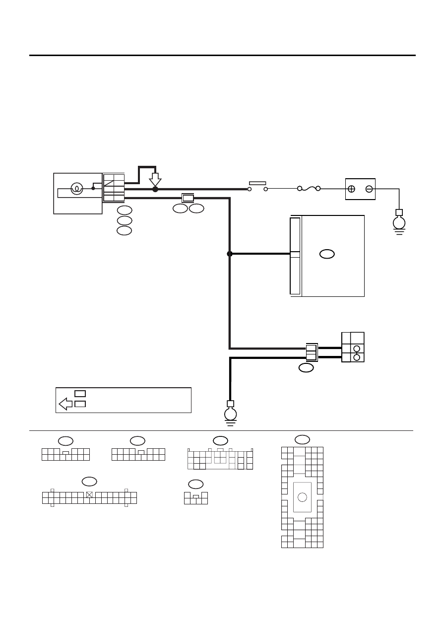
WIRING DIAGRAM:
AT-00789
BATTERY
No.5
IGNITION
RELAY
B55
TCM
B133
SNOW
HOLD MODE
SWITCH
5
16
4
OFF
ON
E
E
i11
1 2 3 4
5 6 7
8 9 10 11 12 13 14 15 16
i12
1 2 3
4 5 6
7 8 9 10 11 12 13 14
B55
1 2 3 4
10 11 12
19 20 21
13
5 6
14 15
7
8
9
16
17
18
22
23
24
COMBINATION
METER
i10
A:
i11
B:
i12
C:
i1
B36
A12
H6
B5
C2
H4
C3
A8
N5
HOLD
H6
H4
: EXCEPT 3.0L MODEL AND TURBO MODEL
: 3.0L MODEL AND TURBO MODEL
H6
H6
B36
B4 B5 B6
A4 A5 A6
C5 C6
F6
D4 D5 D6
F1
H1
C4
G6
G1
C2
K1
M1 M2
K6
L1
D1 D2
A1 A2
B1 B2
I6
J6
L2
I1
J1
H6
M4 M5 M6
L4 L5 L6
N5 N6
O4 O5 O6
N4
P4 P5
N2
O1 O2
P1 P2
N3
O3
P3
P6
A3
B3
C3
E4 E5 E6
E1 E2
i10
1 2 3 4 5 6 7
8 9 10 11 12 13 14
15 16 17 18 19 20 21 22 23 24 25 26 27 28 29 30
B133
1
2
3 4 5 6
AT-145
AUTOMATIC TRANSMISSION (DIAGNOSTICS)
DIAGNOSTIC PROCEDURE FOR NO-DIAGNOSTIC TROUBLE CODE (DTC)
Step
Value
Yes
No
1
CHECK HOLD SWITCH OPERATION.
When hold switch is turned OFF, does LED
light up?
LED lights up.
2
CHECK HOLD SWITCH OPERATION.
When hold switch is turned ON, does LED light
up?
LED lights up.
Go to step Inspec-
tion of SPORT
shift switch. <Ref.
to AT-148,
CHECK SPORT
SHIFT SWITCH.,
Diagnostic Proce-
dure for No-diag-
nostic Trouble
Code (DTC).>
3
CHECK HOLD INDICATOR LIGHT.
1) Turn ignition switch to OFF.
2) Remove combination meter.
3) Remove HOLD indicator light bulb from
combination meter.
Is HOLD indicator light bulb OK?
Bulb is normal.
Replace HOLD
indicator light bulb.
<Ref. to IDI-14,
Combination
Meter Assembly.>
4
CHECK HOLD SWITCH GROUND LINE.
1) Turn ignition switch to OFF.
2) Disconnect connector from hold switch.
3) Measure resistance of harness connector
between hold switch and chassis ground.
Connector & terminal
(B133) No. 4 — Chassis ground:
Is the measured value less than the speci-
fied value?
1
Ω
Repair open circuit
in harness
between hold
switch and chassis
ground.
5
CHECK HOLD SWITCH.
1) Hold switch turned ON.
2) Measure resistance between terminals of
hold switch.
Terminals
No. 4 — No. 5:
Is the measured value less than the speci-
fied value?
1
Ω
Repair hold
switch.
6
CHECK HOLD SWITCH.
1) Hold switch turned OFF.
2) Measure resistance between terminals of
hold switch.
Terminals
No. 4 — No. 5:
Does the measured value exceed the spec-
ified value?
1 M
Ω
Repair hold
switch.
7
CHECK HARNESS CONNECTOR BETWEEN
TCM AND HOLD SWITCH.
1) Disconnect connector TCM and combina-
tion meter.
2) Measure resistance of harness connector
between TCM and hold switch.
Connector & terminal
(B55) No. 16 — (B133) No. 5:
Is the measured value less than the speci-
fied value?
1
Ω
Repair open circuit
in harness
between TCM and
hold switch con-
nector and poor
contact in cou-
pling connector.
Нет комментариевНе стесняйтесь поделиться с нами вашим ценным мнением.
Текст