Subaru Legacy III (2000-2003 year). Service manual — part 603

AT-146
AUTOMATIC TRANSMISSION (DIAGNOSTICS)
DIAGNOSTIC PROCEDURE FOR NO-DIAGNOSTIC TROUBLE CODE (DTC)
8
CHECK HARNESS CONNECTOR BETWEEN
TCM AND COMBINATION METER.
Measure resistance of harness connector TCM
and combination meter.
Connector & terminal
Except 3.0 L model and TURBO model:
(B55) No. 16 — (i12) No. 2:
3.0 L model and TURBO model:
(B55) No. 16 — (i10) No. 12:
Is the measured value less than the specified
value?
1
Ω
Repair open circuit
in harness
between TCM and
combination
meter, and poor
contact in cou-
pling connector.
9
CHECK HARNESS CONNECTOR BETWEEN
TCM AND HOLD SWITCH.
Measure resistance of harness connector
between TCM and chassis ground to make
sure that circuit does not short.
Connector & terminal
(B55) No. 16 — Chassis ground:
Does the measured value exceed the specified
value?
1 M
Ω
Repair short circuit
in harness
between TCM,
hold switch and
combination meter
connector.
10
CHECK INPUT SIGNAL FOR TCM.
1) Connect connectors to TCM and hold
switch.
2) Turn ignition switch ON (with engine OFF).
3) Measure signal voltage for TCM while turn-
ing hold switch OFF.
Connector & terminal
(B55) No. 16 (+) — Chassis ground (–):
Does the measured value exceed the spec-
ified value?
8 V
Replace TCM.
<Ref. to AT-76,
Transmission Con-
trol Module
(TCM).>
11
CHECK INPUT SIGNAL FOR TCM.
Measure signal voltage for TCM while turning
hold switch ON.
Connector & terminal
(B55) No. 16 (+) — Chassis ground (–):
Is the measured value less than the specified
value?
1 V
Replace TCM.
<Ref. to AT-76,
Transmission Con-
trol Module
(TCM).>
12
CHECK POOR CONTACT.
Is there poor contact?
There is poor contact.
Repair poor con-
tact.
A temporary poor
contact of the con-
nector or harness
or connector in
hold switch circuit.
Step
Value
Yes
No
AT-147
AUTOMATIC TRANSMISSION (DIAGNOSTICS)
DIAGNOSTIC PROCEDURE FOR NO-DIAGNOSTIC TROUBLE CODE (DTC)
MEMO:
AT-148
AUTOMATIC TRANSMISSION (DIAGNOSTICS)
DIAGNOSTIC PROCEDURE FOR NO-DIAGNOSTIC TROUBLE CODE (DTC)
J: CHECK SPORT SHIFT SWITCH.
DIAGNOSIS:
SPORT shift switch input signal circuit is open or shorted.
TROUBLE SYMPTOM:
• No SPORT shift mode occurs.
• Does not shift gears in SPORT shift mode.
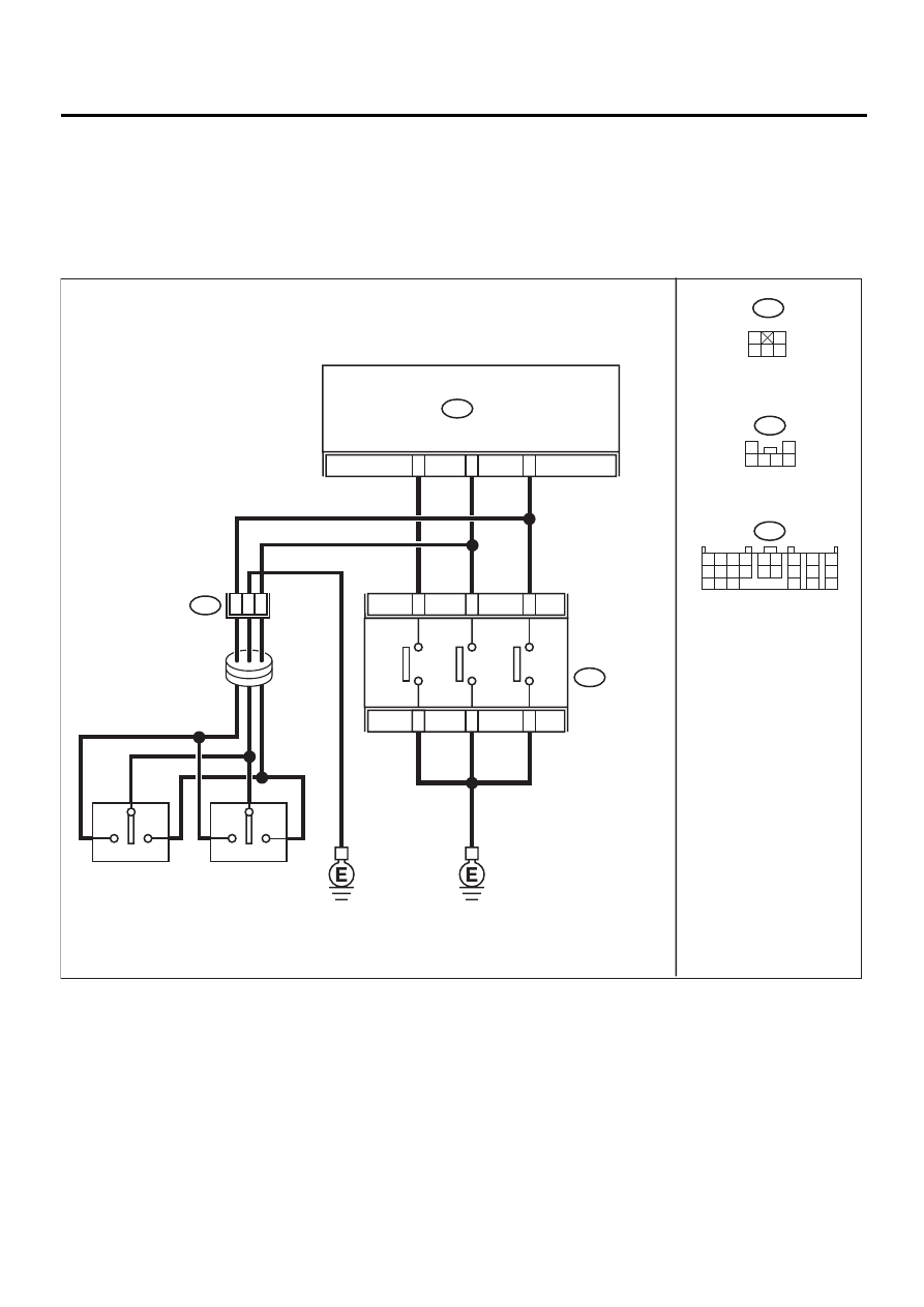
WIRING DIAGRAM:
STEERING
SHIFT SWITCH
AT-00790
15
4
B55
TCM
B237
SPORT SHIFT
SWITCH
B237
1
2
3 4 5 6
B55
1 2
7
8
9
5 6
3 4
10 11 12
19 20 21
13
14 15
16
17
18
22
23
24
SPOR
T SHIFT
MODE SWITCH
6
UP SHIFT
SWITCH
3
5
2
1
13
2
DO
WN SHIFT
SWITCH
B68
1
2
3 4 5
LH
UP
DOWN
B68
3
5
2
STEERING
ROLL
CONNECTOR
RH
UP
DOWN
AT-149
AUTOMATIC TRANSMISSION (DIAGNOSTICS)
DIAGNOSTIC PROCEDURE FOR NO-DIAGNOSTIC TROUBLE CODE (DTC)
Step
Value
Yes
No
1
CHECK VEHICLE.
Is the target model equipped with SPORT
shift?
Model with sport shift
Go to step SYMP-
TOM RELATED
DIAGNOSTIC.
<Ref. to AT-160,
Symptom Related
Diagnostic.>
2
CHECK SPORT SHIFT SWITCH.
Does LED light up when select lever is moved
to SPORT shift mode?
Lights up.
3
CHECK SPORT SHIFT SWITCH.
Does LED light up when select lever is moved
to shift up side?
Lights up.
4
CHECK SPORT SHIFT SWITCH.
Does LED light up when select lever is moved
to shift down side?
Lights up.
5
CHECK STEERING SHIFT SWITCH.
Does LED light up when steering shift switch +
side is pressed?
Lights up.
6
CHECK STEERING SHIFT SWITCH.
Does LED light up when steering shift switch –
side is pressed?
Lights up.
Go to “Inspection
of SPORT shift
indicator” proce-
dures. <Ref. to
AT-156, CHECK
SPORT SHIFT
INDICATOR.,
Diagnostic Proce-
dure for No-diag-
nostic Trouble
Code (DTC).>
7
CHECK SPORT SHIFT SWITCH GROUND
LINE.
1) Turn ignition switch to OFF.
2) Disconnect connector from SPORT shift
switch.
3) Measure resistance of harness between
SPORT shift switch connector and chassis
ground.
Connector & terminal
(B237) No. 4 —- Chassis ground:
Is the measured value less than the speci-
fied value?
1
Ω
Repair open circuit
in harness
between SPORT
shift switch and
chassis ground.
8
CHECK SPORT SHIFT SWITCH.
Measure resistance between SPORT shift
switch terminals.
Connector & terminal
(B237) No. 4 —- No. 5:
Does the measured value exceed the specified
value?
1 M
Ω
Replace lever
plate assembly.
9
CHECK SPORT SHIFT SWITCH.
1) Move select lever to SPORT shift mode.
2) Measure resistance between SPORT shift
switch terminals.
Connector & terminal
(B237) No. 4 — No. 5:
Is the measured value less than the speci-
fied value?
1
Ω
Replace lever
plate assembly.
Нет комментариевНе стесняйтесь поделиться с нами вашим ценным мнением.
Текст