Subaru Legacy III (2000-2003 year). Service manual — part 597
AT-122
AUTOMATIC TRANSMISSION (DIAGNOSTICS)
DIAGNOSTIC PROCEDURE FOR NO-DIAGNOSTIC TROUBLE CODE (DTC)
B: CHECK FWD SWITCH.
DIAGNOSIS:
• LED does not come on even if FWD switch is ON.
• FWD switch circuit is open or shorted.
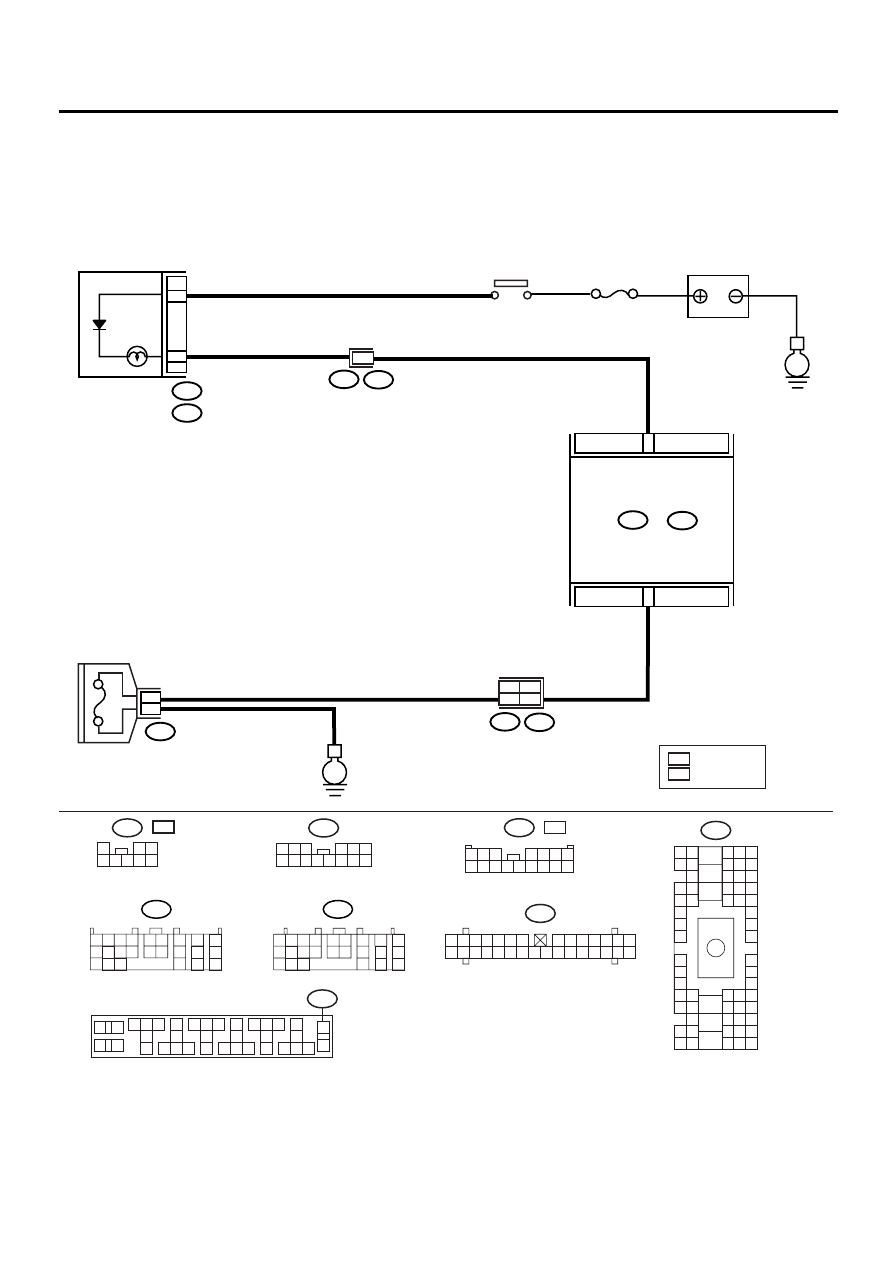
WIRING DIAGRAM:
AT-00786
BATTERY
LH RH
No.5
IGNITION
RELAY
FWD
i10
i1
B36
A:
B55
B:
B56
TCM
C:
C:
i12
F67
COMBINATION
METER
E
FWD
SWITCH
36
35
B55
B56
1 2 3 4
10 11 12
19 20 21
13
5 6
14 15
7
8
9
16
17
18
22
23
24
1 2 3 4
10 11 12
19 20 21
13
5 6
14 15
7
8
9
16
17
18
22
23
24
E
C3
A16
O5
F45
B62
6
8
C2
B20
i10
1 2 3 4 5 6 7
8 9 10 11 12 13 14
15 16 17 18 19 20 21 22 23 24 25 26 27 28 29 30
i12
1 2 3
4 5 6
7 8 9 10 11 12 13 14
B36
B4 B5 B6
A4 A5 A6
C5 C6
F6
D4 D5 D6
F1
H1
C4
G6
G1
C2
K1
M1 M2
K6
L1
D1 D2
A1 A2
B1 B2
I6
J6
L2
I1
J1
H6
M4 M5 M6
L4 L5 L6
N5 N6
O4 O5 O6
N4
P4 P5
N2
O1 O2
P1 P2
N3
O3
P3
P6
A3
B3
C3
E4 E5 E6
E1 E2
1
2
3
4
31
30
34
33
32
28
25
27
26
29
21
20
24
23
22
6
5
7
8
9
18
15
17
16
19
11
10
35
36
F67
14
13
12
: LHD MODEL
LH
: RHD MODEL
RH
1
2 3
4 5 6 7 8
F45
RHD
:
LHD
:
F45
1 2 3
4 5 6 7
8 9 10 11 12 13 14 15 16

AT-123
AUTOMATIC TRANSMISSION (DIAGNOSTICS)
DIAGNOSTIC PROCEDURE FOR NO-DIAGNOSTIC TROUBLE CODE (DTC)
Step
Value
Yes
No
1
CHECK FWD SWITCH.
When fuse is inserted to FWD switch, does
LED light up?
LED lights up.
Go to step CHECK
BRAKE
SWITCH.<Ref. to
AT-125, CHECK
BRAKE SWITCH.,
Diagnostic Proce-
dure for No-diag-
nostic Trouble
Code (DTC).>
2
CHECK FWD INDICATOR LIGHT.
1) Turn ignition switch to OFF.
2) Remove combination meter.
3) Remove FWD indicator light bulb from
combination meter.
Is FWD indicator light bulb OK?
Bulb is normal.
Replace FWD indi-
cator light bulb.
<Ref. to IDI-14,
Combination
Meter Assembly.>
3
CHECK HARNESS CONNECTOR BETWEEN
TCM AND FWD SWITCH.
1) Turn ignition switch to OFF.
2) Disconnect connector from TCM and FWD
switch.
3) Measure resistance of harness between
TCM and FWD switch connector.
Connector & terminal
(B55) No. 20 — (F67) No. 36:
Is the measured value less than the speci-
fied value?
1
Ω
Repair open circuit
in harness
between TCM and
FWD switch con-
nector.
4
CHECK HARNESS CONNECTOR BETWEEN
TCM AND FWD SWITCH.
Measure resistance of harness connector
between TCM and body to make sure that cir-
cuit does not short.
Connector & terminal
(B55) No. 20 — Chassis ground:
Does the measured value exceed the specified
value?
1 M
Ω
Repair short circuit
in harness
between TCM and
FWD switch con-
nector.
5
CHECK HARNESS CONNECTOR BETWEEN
FWD SWITCH AND CHASSIS GROUND.
Measure resistance of harness between FWD
switch and chassis ground.
Connector & terminal
(F67) No. 35 — Chassis ground:
Is the measured value less than the specified
value?
1
Ω
Repair open circuit
in harness
between FWD
switch connector
and chassis
ground.
6
CHECK INPUT SIGNAL FOR TCM.
1) Turn ignition switch to OFF.
2) Connect connector to TCM and FWD
switch.
3) Turn ignition switch to ON.
4) Measure signal voltage for TCM while
installing the fuse to FWD switch connec-
tor.
Connector & terminal
(B55) No. 20 (+) — Chassis ground (
−−−−
):
Is the measured value less than the speci-
fied value?
1 V

AT-124
AUTOMATIC TRANSMISSION (DIAGNOSTICS)
DIAGNOSTIC PROCEDURE FOR NO-DIAGNOSTIC TROUBLE CODE (DTC)
7
CHECK INPUT SIGNAL FOR TCM.
Measure signal voltage for TCM while remov-
ing the fuse from FWD switch connector.
Connector & terminal
(B55) No. 20 (+) — Chassis ground (
−−−−
):
Does the measured value exceed the specified
value?
9 V
Replace TCM.
<Ref. to AT-76,
Transmission Con-
trol Module
(TCM).>
8
CHECK HARNESS CONNECTOR BETWEEN
TCM AND COMBINATION METER.
1) Turn ignition switch to OFF.
2) Disconnect connector from TCM and com-
bination meter.
3) Measure resistance of harness between
TCM and diagnosis connector.
Connector & terminal
(B56) No. 2 — (i10) No. 16:
Is the measured value less than the speci-
fied value?
1
Ω
Repair open circuit
in harness
between TCM and
combination meter
and poor contact
in coupling con-
nector.
9
CHECK HARNESS CONNECTOR BETWEEN
TCM AND COMBINATION METER.
Measure resistance of harness connector
between TCM and chassis ground to make
sure that circuit does not short.
Connector & terminal
(B56) No. 2 — Chassis ground:
Does the measured value exceed the specified
value?
1 M
Ω
Repair short circuit
in harness
between TCM and
combination meter
connector.
10
CHECK OUTPUT SIGNAL EMITTED FROM
TCM.
1) Turn ignition switch to OFF.
2) Connect connector to TCM and combina-
tion meter.
3) Turn ignition switch to ON.
4) Measure signal voltage for TCM while
installing and removing the fuse to FWD
switch connector.
Connector & terminal
(B56) No. 2 — Chassis ground:
Is the measured value less than the speci-
fied value?
1 V
11
CHECK OUTPUT SIGNAL EMITTED FROM
TCM.
Measure signal voltage for TCM while remov-
ing the fuse from FWD switch connector.
Connector & terminal
(B56) No. 2 — Chassis ground:
Does the measured value exceed the specified
value?
9 V
Replace TCM.
<Ref. to AT-76,
Transmission Con-
trol Module
(TCM).>
12
CHECK POOR CONTACT.
Is there poor contact in FWD switch circuit?
There is poor contact.
Repair poor con-
tact.
Replace TCM.
<Ref. to AT-76,
Transmission Con-
trol Module
(TCM).>
Step
Value
Yes
No
AT-125
AUTOMATIC TRANSMISSION (DIAGNOSTICS)
DIAGNOSTIC PROCEDURE FOR NO-DIAGNOSTIC TROUBLE CODE (DTC)
C: CHECK BRAKE SWITCH.
D: CHECK ABS SWITCH.
E: CHECK CRUISE CONTROL SWITCH.
Step
Value
Yes
No
1
CHECK BRAKE SWITCH.
When the brake pedal is depressed, does LED
light up?
LED lights up.
Go to step CHECK
ABS SWITCH.
<Ref. to AT-125,
CHECK ABS
SWITCH., Diag-
nostic Procedure
for No-diagnostic
Trouble Code
(DTC).>
Check brake
switch circuit.
<Ref. to WI-92, A/
T Control Sys-
tem.>
Step
Value
Yes
No
1
CHECK ABS SWITCH.
Does the LED of ABS switch light up?
LED lights up.
Check ABS switch
circuit. <Ref. to
ABS-118, DTC 44
ABS-AT CON-
TROL (NON CON-
TROLLED),
Diagnostics Chart
with Subaru Select
Monitor.> and
<Ref. to ABS-120,
DTC 44 ABS-AT
CONTROL (CON-
TROLLED), Diag-
nostics Chart with
Subaru Select
Monitor.>
Go to step CHECK
CRUISE CON-
TROL SWITCH.
<Ref. to AT-125,
CHECK CRUISE
CONTROL
SWITCH., Diag-
nostic Procedure
for No-diagnostic
Trouble Code
(DTC).>
Step
Value
Yes
No
1
CHECK CRUISE CONTROL SWITCH.
When cruise control is set, does LED light up?
LED lights up.
Go to step CHECK
KICK-DOWN
SWITCH. <Ref. to
AT-126, CHECK
KICK–DOWN
SWITCH., Diag-
nostic Procedure
for No-diagnostic
Trouble Code
(DTC).>
Check cruise con-
trol. <Ref. to CC-
12, Diagnostics
Chart with Symp-
tom.>
Нет комментариевНе стесняйтесь поделиться с нами вашим ценным мнением.
Текст