Subaru Legacy III (2000-2003 year). Service manual — part 598
AT-126
AUTOMATIC TRANSMISSION (DIAGNOSTICS)
DIAGNOSTIC PROCEDURE FOR NO-DIAGNOSTIC TROUBLE CODE (DTC)
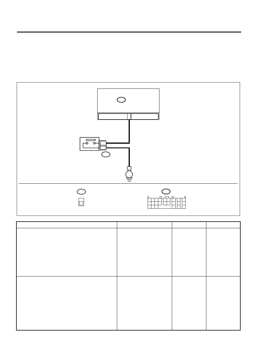
F: CHECK KICK–DOWN SWITCH.
DIAGNOSIS:
• The kick-down switch is not ON when the throttle is fully open but is OFF when the throttle is partially open
or fully closed.
• Kick-down switch circuit is open or shorted.
TROUBLE SYMPTOM:
No kick-down occurs (when the throttle is fully open).
WIRING DIAGRAM:
Step
Value
Yes
No
1
CHECK KICK-DOWN SWITCH OPERATION.
When the accelerator pedal is depressed,
does “ON” displayed?
ON is displayed.
Go to step CHECK
POWER MODE
SWITCH. <Ref. to
AT-128, CHECK
POWER MODE
SWITCH., Diag-
nostic Procedure
for No-diagnostic
Trouble Code
(DTC).>
2
CHECK KICK-DOWN SWITCH GROUND
LINE.
1) Disconnect connector from kick-down
switch.
2) Measure resistance of harness connector
between kick-down switch and chassis
ground.
Connector & terminal
(B129) No. 1 — Chassis ground:
Is the measured value less than the speci-
fied value?
1
Ω
Repair open circuit
in harness
between kick-
down switch and
chassis ground.
AT-00594
E
B55
B55
TCM
KICK-DOWN
SWITCH
B129
1
2
B129
11
1 2 3 4
10 11 12
19 20 21
13
5 6
14 15
7
8
9
16
17
18
22
23
24
1
2

AT-127
AUTOMATIC TRANSMISSION (DIAGNOSTICS)
DIAGNOSTIC PROCEDURE FOR NO-DIAGNOSTIC TROUBLE CODE (DTC)
3
CHECK KICK-DOWN SWITCH.
Measure resistance for kick-down switch when
depressing the accelerator pedal.
Terminals
No. 1 — No. 2:
Is the measured value less than the specified
value?
1
Ω
Replace kick-down
switch.
4
CHECK KICK-DOWN SWITCH.
Measure resistance for kick-down switch when
pressing the accelerator pedal.
Terminals
No. 1 — No. 2:
Does the measured value exceed the specified
value?
1 M
Ω
Replace kick-down
switch.
5
CHECK HARNESS CONNECTOR BETWEEN
TCM AND KICK-DOWN SWITCH.
1) Turn ignition switch OFF.
2) Disconnect connectors from kick-down
switch.
3) Measure resistance of harness connector
between TCM and kick-down switch.
Connector & terminal
(B55) No. 11 — (B129) No. 2:
Is the measured value less than the speci-
fied value?
1
Ω
Repair open circuit
in harness
between TCM and
kick-down switch.
6
CHECK HARNESS CONNECTOR BETWEEN
TCM AND KICK-DOWN SWITCH.
Measure resistance of harness connector
between TCM and chassis ground.
Connector & terminal
(B55) No. 11 — Chassis ground:
Does the measured value exceed the specified
value?
1 M
Ω
Repair short circuit
in harness
between TCM and
chassis ground.
7
CHECK INPUT SIGNAL FOR TCM.
1) Turn ignition switch to OFF.
2) Connect connector to kick-down switch.
3) Turn ignition switch ON (with engine OFF).
4) Measure signal voltage for TCM when
depressing the accelerator pedal.
Connector & terminal
(B55) No. 11 (+) — Chassis ground (
−−−−
):
Is the measured value less than the speci-
fied value?
1 V
8
CHECK INPUT SIGNAL FOR TCM.
Measure signal voltage for TCM when press-
ing the accelerator pedal.
Connector & terminal
(B55) No. 11 (+) — Chassis ground (
−−−−
):
Does the measured value exceed the specified
value?
6.5 V
A temporary poor
contact of the con-
nector and har-
ness may be the
cause. Repair har-
ness and connec-
tor in the TCM.
9
CHECK POOR CONTACT.
Is there poor contact?
There is poor contact.
Repair poor con-
tact.
Replace TCM.
<Ref. to AT-76,
Transmission Con-
trol Module
(TCM).>
Step
Value
Yes
No
AT-128
AUTOMATIC TRANSMISSION (DIAGNOSTICS)
DIAGNOSTIC PROCEDURE FOR NO-DIAGNOSTIC TROUBLE CODE (DTC)
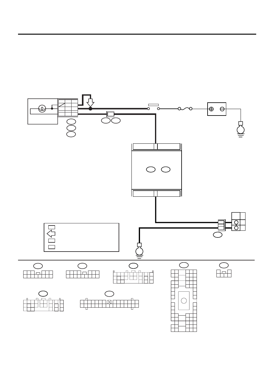
G: CHECK POWER MODE SWITCH.
DIAGNOSIS:
• LED does not come on when power switch is ON.
• Power switch circuit is open or shorted.
TROUBLE SYMPTOM:
No power mode occurs.
WIRING DIAGRAM:
AT-00787
BATTERY
No.5
IGNITION
RELAY
i11
1 2 3 4
5 6 7
8 9 10 11 12 13 14 15 16
i12
1 2 3
4 5 6
7 8 9 10 11 12 13 14
B55
TCM
B:
B56
B133
C:
POWER
MODE
SWITCH
ON
OFF
E
E
B55
B56
1 2 3 4
10 11 12
19 20 21
13
5 6
14 15
7
8
9
16
17
18
22
23
24
1 2 3 4
10 11 12
19 20 21
13
5 6
14 15
7
8
9
16
17
18
22
23
24
COMBINATION
METER
i10
A:
i11
B:
i12
C:
i1
B36
B12
H6L
A8
B6
H4N
C3
B5
P5
POWER
H6RT : RHD 3.0L MODEL AND TURBO MODEL
H6L : LHD 3.0L MODEL
H4N : EXCEPT 3.0L MODEL AND TURBO MODEL
: 3.0L MODEL AND TURBO MODEL
H6
H6
B36
B4 B5 B6
A4 A5 A6
C5 C6
F6
D4 D5 D6
F1
H1
C4
G6
G1
C2
K1
M1 M2
K6
L1
D1 D2
A1 A2
B1 B2
I6
J6
L2
I1
J1
H6
M4 M5 M6
L4 L5 L6
N5 N6
O4 O5 O6
N4
P4 P5
N2
O1 O2
P1 P2
N3
O3
P3
P6
A3
B3
C3
E4 E5 E6
E1 E2
i10
1 2 3 4 5 6 7
8 9 10 11 12 13 14
15 16 17 18 19 20 21 22 23 24 25 26 27 28 29 30
B133
1
2
3 4 5 6
A13
H6RT
B5
A8
C11
B23
3
4

AT-129
AUTOMATIC TRANSMISSION (DIAGNOSTICS)
DIAGNOSTIC PROCEDURE FOR NO-DIAGNOSTIC TROUBLE CODE (DTC)
Step
Value
Yes
No
1
CHECK POWER SWITCH OPERATION.
When power switch is turned OFF, does LED
light up?
LED lights up.
2
CHECK POWER SWITCH OPERATION.
When power switch is turned ON, does LED
light up?
LED lights up.
Go to step CHECK
INHIBITOR
SWITCH. <Ref. to
AT-132, CHECK
INHIBITOR
SWITCH., Diag-
nostic Procedure
for No-diagnostic
Trouble Code
(DTC).>
3
CHECK POWER INDICATOR LIGHT.
1) Turn ignition switch to OFF.
2) Remove combination meter.
3) Remove POWER indicator light bulb from
combination meter.
Is POWER indicator light bulb OK?
Bulb is normal.
Replace POWER
indicator light bulb.
<Ref. to IDI-14,
Combination
Meter Assembly.>
4
CHECK POWER SWITCH GROUND LINE.
1) Turn ignition switch to OFF.
2) Disconnect connector from power switch.
3) Measure resistance of harness connector
between power switch and chassis ground.
Connector & terminal
(B133) No. 4 — Chassis ground:
Is the measured value less than the speci-
fied value?
1
Ω
Repair open circuit
in harness
between power
switch and chassis
ground.
5
CHECK POWER SWITCH.
1) Power switch turned ON.
2) Measure resistance between terminals of
power switch.
Terminals
No. 3 — No. 4:
Is the measured value less than the speci-
fied value?
1
Ω
Repair power
switch.
6
CHECK POWER SWITCH.
1) Power switch turned OFF.
2) Measure resistance between terminals of
power switch.
Terminals
No. 3 — No. 4:
Does the measured value exceed the spec-
ified value?
1 M
Ω
Repair power
switch.
7
CHECK HARNESS CONNECTOR BETWEEN
TCM AND POWER SWITCH.
Measure resistance of harness connector
between TCM and power switch.
Connector & terminal
(B55) No. 23 — (B133) No. 3:
Is the measured value less than the specified
value?
1
Ω
Repair open circuit
in harness
between TCM and
power switch con-
nector.
Нет комментариевНе стесняйтесь поделиться с нами вашим ценным мнением.
Текст