Subaru Legacy III (2000-2003 year). Service manual — part 160

EN(H4SO)-252
ENGINE (DIAGNOSTICS)
DIAGNOSTIC PROCEDURE WITH DIAGNOSTIC TROUBLE CODE (DTC)
BK:DTC P0741 — TORQUE CONVERTER CLUTCH CIRCUIT PERFORMANCE
OR STUCK OFF —
• DTC DETECTING CONDITION:
• Two consecutive driving cycles with fault
• TROUBLE SYMPTOM:
• No lock-up (after engine warm-up)
• No shift or excessive tight corner “braking”
CAUTION:
After repair or replacement of faulty parts, conduct Clear Memory Mode<Ref. to EN(H4SO)-47, OPER-
ATION, Clear Memory Mode.> and Inspection Mode <Ref. to EN(H4SO)-40, OPERATION, Inspection
Mode.> .
Step
Value
Yes
No
1
CHECK ANY OTHER DTC ON DISPLAY.
Is any other DTC displayed?
DTC indicated.
Inspect the rele-
vant DTC using
“List of Diagnostic
Trouble Code
(DTC)”. <Ref. to
EN(H4SO)-83, List
of Diagnostic
Trouble Code
(DTC).>
2
CHECK LOCK-UP DUTY SOLENOID CIR-
CUIT.
Check lock-up duty solenoid circuit.
Is there any trouble in lock-up duty solenoid
circuit?
<Ref. to AT-96, DTC 77 LOCK-UP DUTY
SOLENOID, Diagnostic Procedure with Diag-
nostic Trouble Code (DTC).>
There is a fault.
Repair or replace
lock-up duty sole-
noid circuit.
3
CHECK THROTTLE POSITION SENSOR
CIRCUIT.
Check throttle position sensor circuit.
Is there any trouble in throttle position sensor
circuit?
<Ref. to AT-52, DTC 31 THROTTLE POSI-
TION SENSOR, Diagnostic Procedure with
Diagnostic Trouble Code (DTC).>
There is a fault.
Repair or replace
throttle position
sensor circuit.
4
CHECK TORQUE CONVERTER TURBINE
SPEED SENSOR CIRCUIT.
Check torque converter turbine speed sensor
circuit.
Is there any trouble in torque converter turbine
speed sensor circuit?
<Ref. to AT-64, DTC 36 TORQUE CON-
VERTER TURBINE SPEED SENSOR, Diag-
nostic Procedure with Diagnostic Trouble
Code (DTC).>
There is a fault.
Repair or replace
torque converter
turbine speed sen-
sor circuit.
5
CHECK ENGINE SPEED INPUT CIRCUIT.
Check engine speed input circuit.
Is there any trouble in engine speed input cir-
cuit?
<Ref. to AT-42, DTC 11 ENGINE SPEED
SIGNAL, Diagnostic Procedure with Diagnostic
Trouble Code (DTC).>
There is a fault.
Repair or replace
engine speed
input circuit.

EN(H4SO)-253
ENGINE (DIAGNOSTICS)
DIAGNOSTIC PROCEDURE WITH DIAGNOSTIC TROUBLE CODE (DTC)
6
CHECK INHIBITOR SWITCH CIRCUIT.
Check inhibitor switch circuit.
Is there any trouble in inhibitor switch circuit?
<Ref. to AT-132, CHECK INHIBITOR
SWITCH., Diagnostic Procedure for No-diag-
nostic Trouble Code (DTC).>
There is a fault.
Repair or replace
inhibitor switch cir-
cuit.
7
CHECK BRAKE LIGHT SWITCH CIRCUIT.
Check brake light switch circuit.
Is there any trouble in brake light switch cir-
cuit?
<Ref. to AT-125, CHECK BRAKE SWITCH.,
Diagnostic Procedure for No-diagnostic Trou-
ble Code (DTC).>
There is a fault.
Repair or replace
brake light switch
circuit.
8
CHECK ATF TEMPERATURE SENSOR CIR-
CUIT.
Check ATF temperature sensor circuit.
Is there any trouble in ATF temperature sensor
circuit?
<Ref. to AT-48, DTC 27 ATF TEMPERATURE
SENSOR, Diagnostic Procedure with Diagnos-
tic Trouble Code (DTC).>
There is a fault.
Repair or replace
ATF temperature
sensor circuit.
9
CHECK POOR CONTACT.
Check poor contact in TCM connector.
Is there poor contact in TCM connector?
There is poor contact.
Repair poor con-
tact in TCM con-
nector.
10
CHECK MECHANICAL TROUBLE.
Check mechanical trouble in automatic trans-
mission.
Is there any mechanical trouble in automatic
transmission?
There is mechanical trouble.
Repair or replace
automatic trans-
mission. <Ref. to
AT-32, INSPEC-
TION, Road Test.>
Replace TCM.
<Ref. to AT-76,
Transmission Con-
trol Module
(TCM).>
Step
Value
Yes
No
EN(H4SO)-254
ENGINE (DIAGNOSTICS)
DIAGNOSTIC PROCEDURE WITH DIAGNOSTIC TROUBLE CODE (DTC)
BL:DTC P0851 — NEUTRAL SWITCH INPUT CIRCUIT LOW (AT MODEL) —
• DTC DETECTING CONDITION:
• Two consecutive driving cycles with fault
• TROUBLE SYMPTOM:
• Erroneous idling
CAUTION:
After repair or replacement of faulty parts, conduct Clear Memory Mode<Ref. to EN(H4SO)-47, OPER-
ATION, Clear Memory Mode.> and Inspection Mode <Ref. to EN(H4SO)-40, OPERATION, Inspection
Mode.> .
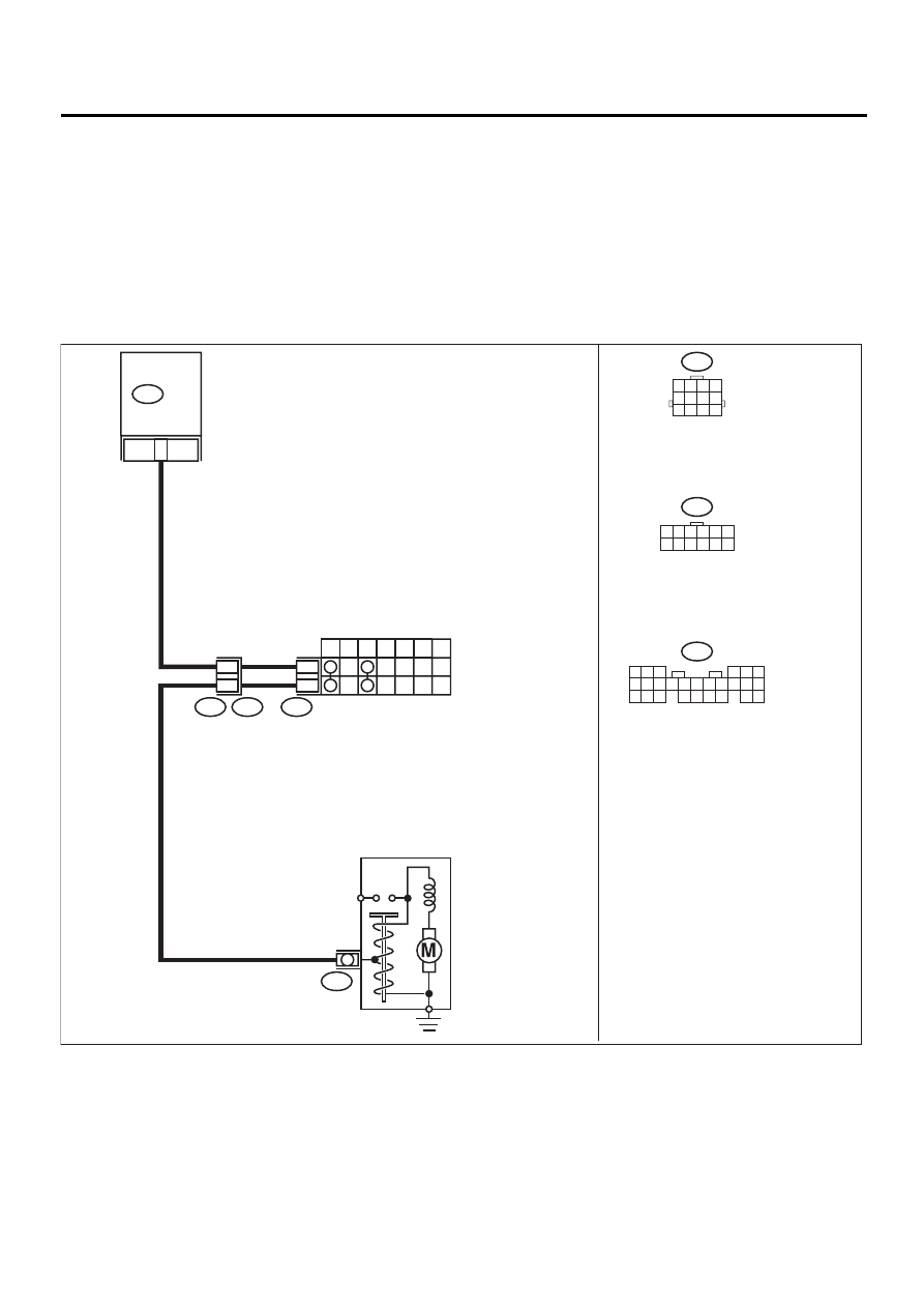
• WIRING DIAGRAM:
EN-00740
12
INHIBITOR SWITCH
7
P
R
N
D
3
2
1
12
11
T7
T3
B12
B14
B12
T7
1 2 3 4 5 6
7 8 9 10 11 12
21
B136
ECM
STARTER MOTOR
1 2 3 4
5 6 7 8
9 10 11 12
B136
5 6
7
2
1
9
8
4
3
23
21 22
24
10 11 12 13 14
25 26
15 16 17
18 19 20

EN(H4SO)-255
ENGINE (DIAGNOSTICS)
DIAGNOSTIC PROCEDURE WITH DIAGNOSTIC TROUBLE CODE (DTC)
Step
Value
Yes
No
1
CHECK ANY OTHER DTC ON DISPLAY.
Is any other DTC displayed?
DTC indicated.
Inspect the rele-
vant DTC using
“List of Diagnos-
tics Trouble Code
(DTC)”. <Ref. to
EN(H4SO)-83, List
of Diagnostic
Trouble Code
(DTC).>
2
CHECK INPUT SIGNAL FOR ECM.
1) Turn ignition switch to ON.
2) Measure voltage between ECM and chas-
sis ground.
Connector & terminal
(B136) No. 21 (+) — Chassis ground (
−−−−
):
Is the measured value within the specified
value at except “N” and “P” position?
4.5 V - 5.5 V
Even if MI lights
up, the circuit has
returned to a nor-
mal condition at
this time.
3
CHECK HARNESS BETWEEN ECM AND
TRANSMISSION HARNESS CONNECTOR.
1) Turn ignition switch to OFF.
2) Disconnect connectors from ECM and
transmission harness connector (T3).
3) Measure resistance of harness between
ECM connector and chassis ground.
Connector & terminal
(B136) No. 21 — Chassis ground:
Does the measured value exceed the spec-
ified value?
1 M
Ω
Repair ground
short circuit in har-
ness between
ECM and trans-
mission harness
connector.
4
CHECK TRANSMISSION HARNESS CON-
NECTOR.
1) Disconnect connector from inhibitor switch.
2) Measure resistance of harness between
transmission harness connector and
engine ground.
Connector & terminal
(T3) No. 12 — Engine ground:
Does the measured value exceed the spec-
ified value?
1 M
Ω
Repair ground
short circuit in har-
ness between
transmission har-
ness and inhibitor
switch connector.
5
CHECK INHIBITOR SWITCH.
Measure resistance between inhibitor switch
connector receptacle's terminals in select lever
except for “N” position.
Terminals
No. 7 — No. 12:
Does the measured value exceed the specified
value at except "N" and "P" positions?
1 M
Ω
Replace inhibitor
switch. <Ref. to
AT-49, Inhibitor
Switch.>
6
CHECK SELECTOR CABLE CONNECTION.
Is there any fault in selector cable connection
to inhibitor switch?
There is a fault.
Repair selector
cable connection.
<Ref. to CS-12,
Select Cable.>
Contact SUBARU
distributor service.
NOTE:
Inspection by DTM
is required, be-
cause probable
cause is deteriora-
tion of multiple
parts.
Нет комментариевНе стесняйтесь поделиться с нами вашим ценным мнением.
Текст