Subaru Legacy III (2000-2003 year). Service manual — part 161
EN(H4SO)-256
ENGINE (DIAGNOSTICS)
DIAGNOSTIC PROCEDURE WITH DIAGNOSTIC TROUBLE CODE (DTC)
BM:DTC P0851 — NEUTRAL SWITCH INPUT CIRCUIT LOW (MT MODEL) —
• DTC DETECTING CONDITION:
• Two consecutive driving cycles with fault
• TROUBLE SYMPTOM:
• Erroneous idling
CAUTION:
After repair or replacement of faulty parts, conduct Clear Memory Mode<Ref. to EN(H4SO)-47, OPER-
ATION, Clear Memory Mode.> and Inspection Mode <Ref. to EN(H4SO)-40, OPERATION, Inspection
Mode.> .
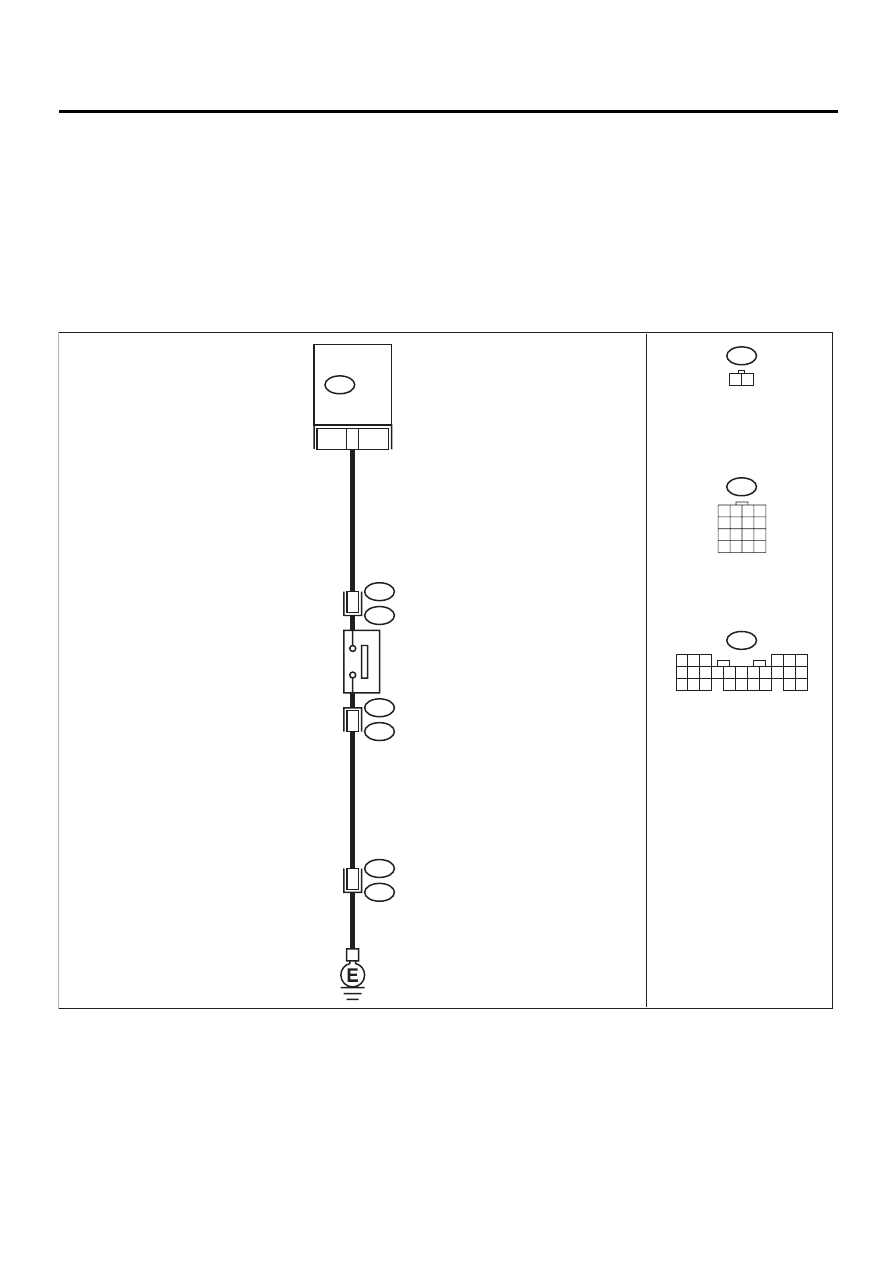
• WIRING DIAGRAM:
EN-01137
2
1
21
B136
ECM
NEUTRAL
POSITION
SWITCH
B25
T2
T2
B25
B22
E3
15
B25
1 2
B22
1 2 3 4
5 6 7 8
9 10 11 12
13 14 15 16
B136
5 6
7
2
1
9
8
4
3
23
21 22
24
10 11 12 13 14
25 26
15 16 17
18 19 20
EN(H4SO)-257
ENGINE (DIAGNOSTICS)
DIAGNOSTIC PROCEDURE WITH DIAGNOSTIC TROUBLE CODE (DTC)
Step
Value
Yes
No
1
CHECK INPUT SIGNAL FOR ECM.
1) Turn ignition switch to ON.
2) Measure voltage between ECM and chas-
sis ground.
Connector & terminal
(B136) No. 21 (+) — Chassis ground (
−−−−
):
Does the measured value exceed the spec-
ified value in neutral position?
5 V
2
CHECK INPUT SIGNAL FOR ECM.
Measure voltage between ECM and chassis
ground.
Connector & terminal
(B136) No. 21 (+) — Chassis ground (
−−−−
):
Is the measured value less than the specified
value at except neutral position?
1 V
3
CHECK POOR CONTACT.
Check poor contact in ECM connector.
Is there poor contact in ECM connector?
There is poor contact.
Repair poor con-
tact in ECM con-
nector.
Contact SUBARU
distributor service.
NOTE:
Inspection by DTM
is required, be-
cause probable
cause is deteriora-
tion of multiple
parts.
4
CHECK NEUTRAL POSITION SWITCH.
1) Turn ignition switch to OFF.
2) Disconnect connector from transmission
harness.
3) Measure resistance between transmission
harness and connector terminals.
Connector & terminal
(T2) No. 1 — No. 2:
Does the measured value exceed the spec-
ified value in neutral position?
1 M
Ω
Repair short circuit
in transmission
harness or replace
neutral position
switch.
5
CHECK HARNESS BETWEEN ECM AND
NEUTRAL POSITION SWITCH CONNEC-
TOR.
1) Disconnect connector from ECM.
2) Measure resistance between ECM and
chassis ground.
Connector & terminal
(B136) No. 21 — Chassis ground:
Does the measured value exceed the spec-
ified value?
1 M
Ω
Repair ground
short circuit in har-
ness between
ECM and trans-
mission harness
connector.
6
CHECK POOR CONTACT.
Check poor contact in transmission harness
connector.
Is there poor contact in transmission harness
connector?
There is poor contact.
Repair poor con-
tact in transmis-
sion harness
connector.
Contact SUBARU
distributor service.
NOTE:
Inspection by DTM
is required, be-
cause probable
cause is deteriora-
tion of multiple
parts.
EN(H4SO)-258
ENGINE (DIAGNOSTICS)
DIAGNOSTIC PROCEDURE WITH DIAGNOSTIC TROUBLE CODE (DTC)
BN:DTC P0852 — NEUTRAL SWITCH INPUT CIRCUIT HIGH (AT MODEL) —
• DTC DETECTING CONDITION:
• Two consecutive driving cycles with fault
• TROUBLE SYMPTOM:
• Erroneous idling
CAUTION:
After repair or replacement of faulty parts, conduct Clear Memory Mode<Ref. to EN(H4SO)-47, OPER-
ATION, Clear Memory Mode.> and Inspection Mode <Ref. to EN(H4SO)-40, OPERATION, Inspection
Mode.> .
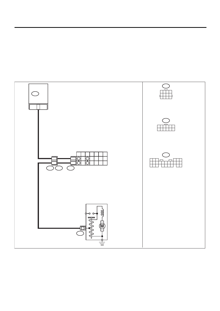
• WIRING DIAGRAM:
EN-00740
12
INHIBITOR SWITCH
7
P
R
N
D
3
2
1
12
11
T7
T3
B12
B14
B12
T7
1 2 3 4 5 6
7 8 9 10 11 12
21
B136
ECM
STARTER MOTOR
1 2 3 4
5 6 7 8
9 10 11 12
B136
5 6
7
2
1
9
8
4
3
23
21 22
24
10 11 12 13 14
25 26
15 16 17
18 19 20
EN(H4SO)-259
ENGINE (DIAGNOSTICS)
DIAGNOSTIC PROCEDURE WITH DIAGNOSTIC TROUBLE CODE (DTC)
Step
Value
Yes
No
1
CHECK ANY OTHER DTC ON DISPLAY.
Is any other DTC displayed?
DTC indicated.
Inspect the rele-
vant DTC using
“List of Diagnos-
tics Trouble Code
(DTC)”. <Ref. to
EN(H4SO)-83, List
of Diagnostic
Trouble Code
(DTC).>
2
CHECK INPUT SIGNAL FOR ECM.
1) Turn ignition switch to ON.
2) Measure voltage between ECM and chas-
sis ground in select level “N” and “P” posi-
tions.
Connector & terminal
(B136) No. 21 (+) — Chassis ground
Is the measured value less than the speci-
fied value?
1 V
3
CHECK INPUT SIGNAL FOR ECM.
Measure voltage between ECM and chassis
ground in select level “N” and “P” positions.
Connector & terminal
(B136) No. 21 (+) — Chassis ground
Is the measured value within the specified
range?
4.5 - 5.5 V
4
CHECK POOR CONTACT.
Check poor contact in ECM connector.
Is there poor contact in ECM connector.
There is poor contact.
Repair poor con-
tact in ECM con-
nector.
Contact SUBARU
distributor service.
NOTE:
Inspection by DTM
is required, be-
cause probable
cause is deteriora-
tion of multiple
parts.
5
CHECK HARNESS BETWEEN ECM AND IN-
HIBITOR SWITCH CONNECTOR.
1) Turn ignition switch to OFF.
2) Disconnect connector from ECM and inhibi-
tor switch.
3) Measure resistance of harness between
ECM and inhibitor switch connector.
Connector & terminal
(B136) No. 21 — (T7) No. 12:
Is the measured value less than the speci-
fied value?
1
Ω
Repair harness
and connector.
NOTE:
In this case, repair
the following:
• Open circuit in
harness between
ECM and inhibitor
switch connector
• Poor contact in
coupling connector
• Poor contact in
inhibitor switch
connector
• Poor contact in
ECM connector
Нет комментариевНе стесняйтесь поделиться с нами вашим ценным мнением.
Текст