Subaru Legacy III (2000-2003 year). Service manual — part 427
ME(H4DOSTC)-72
MECHANICAL
CYLINDER BLOCK
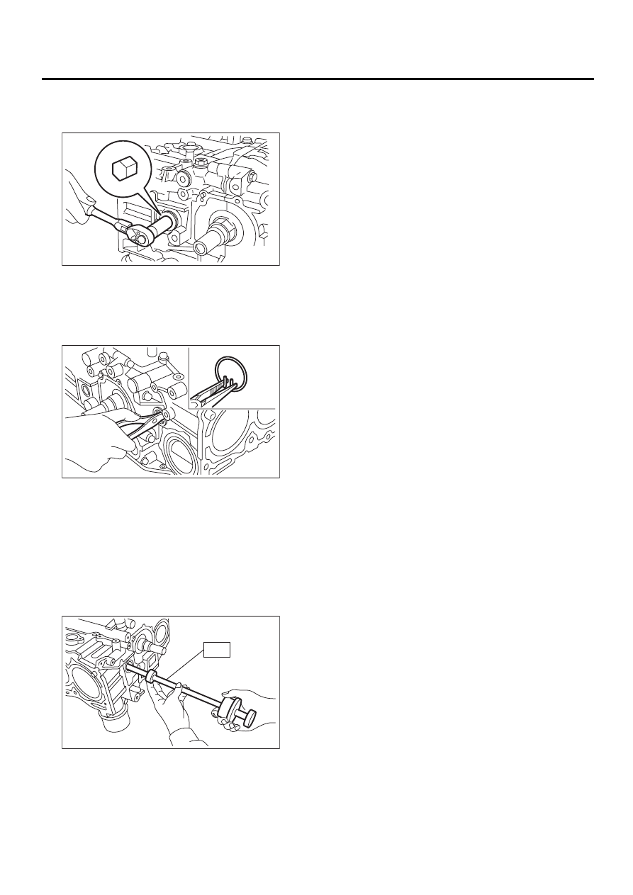
24) Remove the service hole cover and service
hole plugs using hexagon wrench [14 mm (0.55
in)].
25) Rotate the crankshaft to bring #1 and #2 pis-
tons to bottom dead center position, and then re-
move the piston circlip through service hole of #1
and #2 cylinders.
ST
499897200
PISTON CIRCLIP PLIERS
26) Draw out the piston pin from #1 and #2 pistons
using ST.
ST
499097600
PISTON PIN REMOVER (MT
vehicles)
ST
499097700
PISTON PIN REMOVER (AT
vehicles)
NOTE:
Be careful not to confuse the original combination
of piston, piston pin and cylinder.
27) Similarly remove the piston pins from #3 and #4
pistons.
28) Remove the bolts which connect cylinder block
on the side of #2 and #4 cylinders.
29) Back off the bolts which connect cylinder block
on the side of #1 and #3 cylinders two or three
turns.
30) Set up the cylinder block so that #1 and #3 cyl-
inders are on the upper side, then remove the cyl-
inder block connecting bolts.
31) Separate the cylinder blocks (LH) and (RH).
NOTE:
When separating the cylinder block, do not allow
the connecting rod to fall and damage the cylinder
block.
ME-00140
ME-00141
ME-00142
ST
ME(H4DOSTC)-73
MECHANICAL
CYLINDER BLOCK
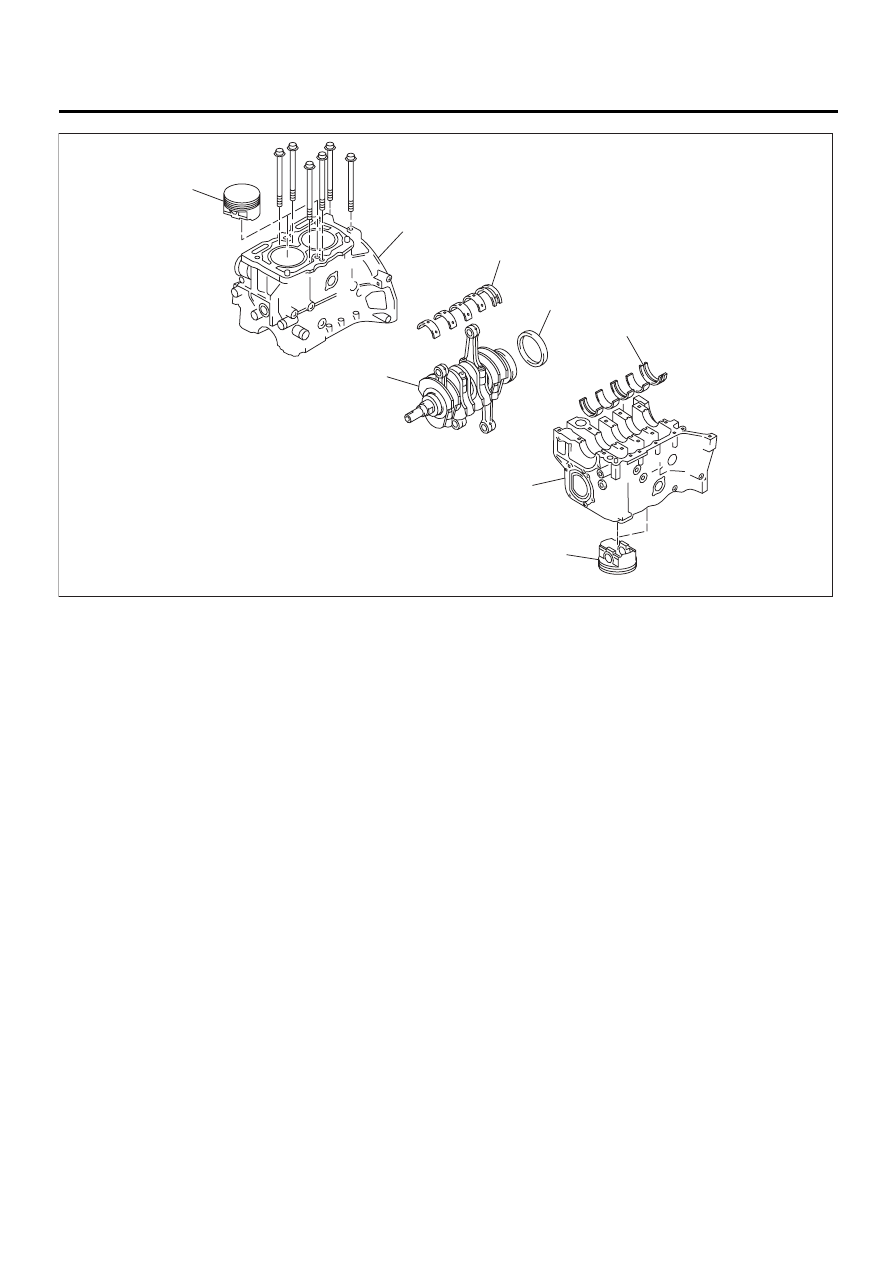
32) Remove the rear oil seal.
33) Remove the crankshaft together with connect-
ing rod.
34) Remove the crankshaft bearings from cylinder
block using a hammer handle.
NOTE:
Do not confuse the combination of crankshaft bear-
ings. Press the bearing at the end opposite to lock-
ing lip.
35) Draw out each piston from cylinder block using
a wooden bar or hammer handle.
NOTE:
Do not confuse the combination of piston and cylin-
der.
(1) Cylinder block
(3) Crankshaft
(5) Piston
(2) Rear oil seal
(4) Crankshaft bearing
ME-00143
( 1 )
( 1 )
( 2 )
( 3 )
( 4 )
( 4 )
( 5 )
( 5 )
ME(H4DOSTC)-74
MECHANICAL
CYLINDER BLOCK
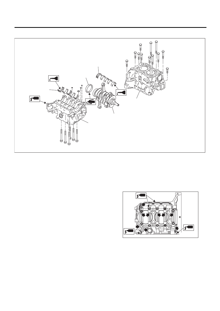
B: INSTALLATION
1) Remove oil in the mating surface of bearing and
cylinder block before installation. Also apply a coat
of engine oil to crankshaft pins.
2) Position the crankshaft on #2 and #4 cylinder
block.
3) Apply fluid packing to the mating surface of #1
and #3 cylinder block, and position it on #2 and #4
cylinder block.
Fluid packing:
Part No. 004403007
THREE BOND 1215 or equivalent
NOTE:
Do not allow fluid packing to jut into O-ring grooves,
oil passages, bearing grooves, etc.
(1) Crankshaft bearing
(3) Cylinder block
(4) Rear oil seal
(2) Crankshaft
ME-00144
( 1 )
( 1 )
( 2 )
( 3 )
( 3 )
( 4 )
ME-00145
ME(H4DOSTC)-75
MECHANICAL
CYLINDER BLOCK
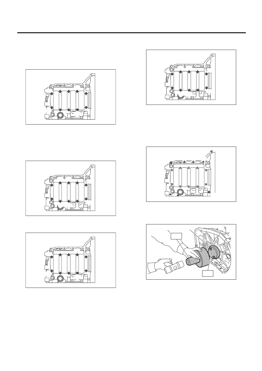
4) Tighten the 10 mm cylinder block connecting
bolts in alphabetical sequence shown in the figure.
(LH side)
Tightening torque:
15 N·m (1.5 kgf-m, 10.8 ft-lb)
5) Tighten the 10 mm cylinder block connecting
bolts in alphabetical sequence shown in the figure.
(RH side)
Tightening torque:
15 N·m (1.5 kgf-m, 10.8 ft-lb)
6) Further tighten the LH side bolts (A — D) to 90
°
in alphabetical sequence.
7) Further tighten the RH side bolts (E — J) to 90
°
in alphabetical sequence.
8) Tighten the 8 mm and 6 mm cylinder block con-
necting bolts in alphabetical sequence shown in the
figure.
Tightening torque:
(A) — (G): 25 N·m (2.5 kgf-m, 18.1 ft-lb)
(H): 6.4 N·m (0.65 kgf-m, 4.7 ft-lb)
9) Install the rear oil seal using ST1 and ST2.
ST1
499597100
OIL SEAL GUIDE
ST2
499587200
OIL SEAL INSTALLER
10) Position the top ring gap at (A) or (B) in the fig-
ure.
( A )
( B )
( C )
( D )
ME-00398
( F )
( E )
( I )
( G )
( H )
( J )
ME-00399
( A )
( B )
( C )
( D )
ME-00398
(A) Rear oil seal
(B) Flywheel attaching bolt
( F )
( E )
( I )
( G )
( H )
( J )
ME-00399
ME-00147
( A )
( B )
( C )
( D )
( E )
( F )
( G )
( H )
ME-00148
( A )
( B )
ST1
ST2
Нет комментариевНе стесняйтесь поделиться с нами вашим ценным мнением.
Текст