Subaru Legacy III (2000-2003 year). Service manual — part 425
ME(H4DOSTC)-64
MECHANICAL
CYLINDER HEAD ASSEMBLY
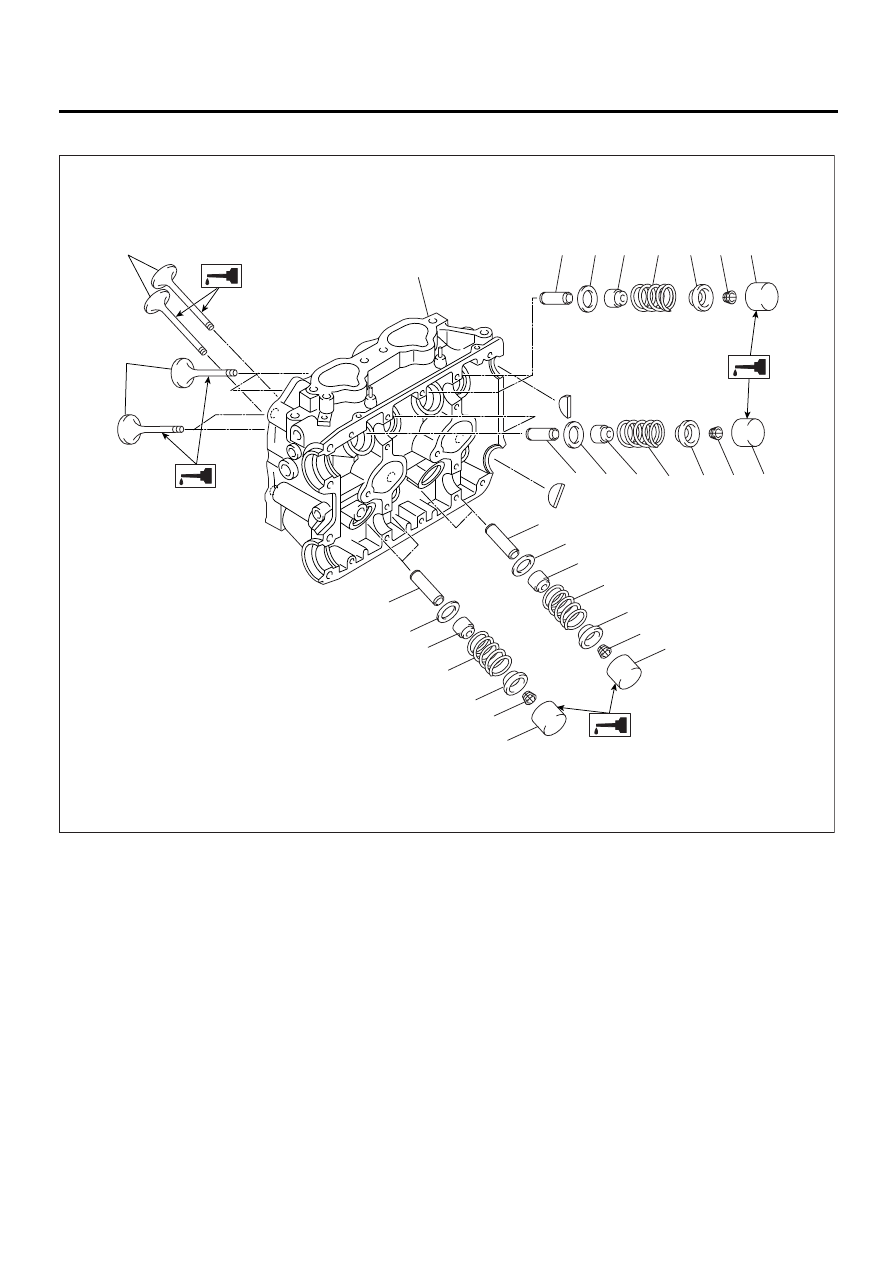
D: ASSEMBLY
(1) Exhaust valve
(5) Intake valve oil seal
(9) Valve lifter
(2) Intake valve
(6) Valve spring
(10) Exhaust valve oil seal
(3) Cylinder head
(7) Retainer
(11) Intake valve guide
(4) Valve spring seat
(8) Retainer key
(12) Exhaust valve guide
ME-00003
(3)
(1)
(2)
(11)
(4)
(5)
(6)
(7)
(8)
(9)
(11)
(12)
(12)
(10)
(4)
(4)
(5)
(6)
(6)
(7)
(7)
(8)
(8)
(9)
(9)
(10)
(4)
(6)
(7)
(8)
(9)
ME(H4DOSTC)-65
MECHANICAL
CYLINDER HEAD ASSEMBLY
1) Installation of valve spring and valve:
(1) Coat the stem of each valve with engine oil
and insert the valve into valve guide.
NOTE:
When inserting the valve into valve guide, use spe-
cial care not to damage the oil seal lip.
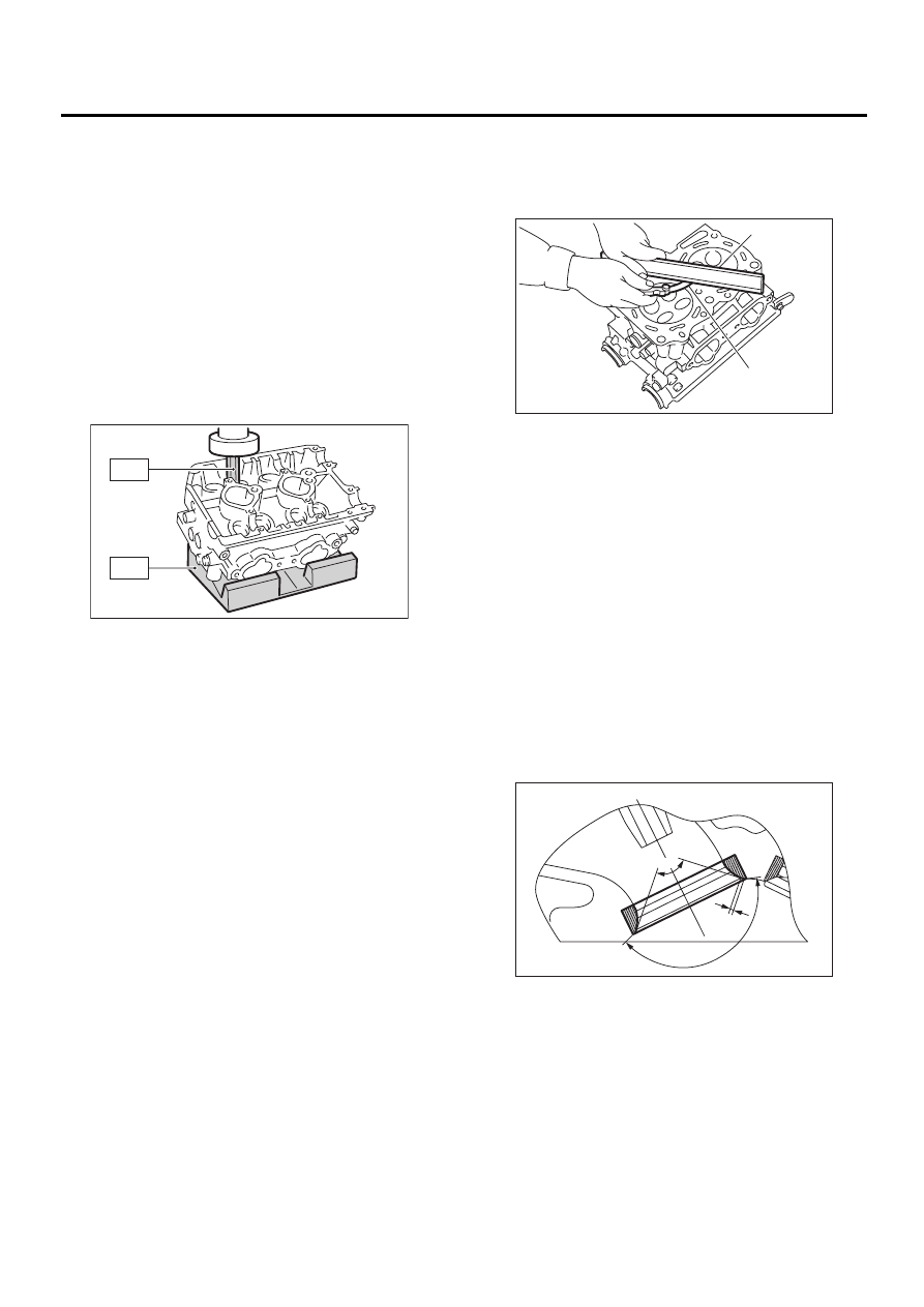
(2) Set the cylinder head on ST1.
(3) Install the valve spring and retainer using
ST2.
ST1
498267600
CYLINDER HEAD TABLE
ST2
499718000
VALVE SPRING REMOVER
NOTE:
Be sure to install the valve springs with their close-
coiled end facing the seat on the cylinder head.
(4) Compress the valve spring, and then fit the
valve spring retainer key.
(5) After installing, tap the valve spring retainers
lightly with wooden hammer for better seating.
2) Apply oil to the surface of the valve lifter.
3) Install the valve lifter.
E: INSPECTION
1. CYLINDER HEAD
1) Make sure that no crack or other damage exists.
In addition to visual inspection, inspect the impor-
tant areas by means of red check.
2) Measure the warping of the cylinder head sur-
face that mates with crankcase by using a straight
edge (A) and thickness gauge (B).
If the warping exceeds 0.05 mm (0.0020 in), re-
grind the surface with a surface grinder.
Warping limit:
0.05 mm (0.0020 in)
Grinding limit:
0.3 mm (0.012 in)
Standard height of cylinder head:
127.5 mm (5.02 in)
NOTE:
Uneven torque for the cylinder head nuts can
cause warping. When reassembling, pay special
attention to the torque so as to tighten evenly.
2. VALVE SEAT
Inspect the intake and exhaust valve seats, and
then correct the contact surfaces with valve seat
cutter if they are defective or when valve guides are
replaced.
Valve seat width: W
Intake
Standard
1.0 mm (0.039 in)
Limit
1.7 mm (0.067 in)
Exhaust
Standard
1.5 mm (0.059 in)
Limit
2.2 mm (0.087 in)
ME-00124
ST2
ST1
ME-00126
( A )
( B )
ME-00127
w
90
˚
150
˚
ME(H4DOSTC)-66
MECHANICAL
CYLINDER HEAD ASSEMBLY
3. VALVE GUIDE
1) Check the clearance between valve guide and
stem. The clearance can be checked by measuring
the outside diameter of valve stem and the inside
diameter of valve guide with outside and inside mi-
crometers respectively.
Clearance between the valve guide and valve
stem:
Standard
Intake
0.030 — 0.057 mm (0.0012 — 0.0022 in)
Exhaust
0.040 — 0.067 mm (0.0016 — 0.0026 in)
Limit
0.15 mm (0.0059 in)
2) If the clearance between valve guide and stem
exceeds the limit, replace the valve guide or valve
itself whichever shows greater amount of wear.
See the following procedure for valve guide re-
placement.
Valve guide inner diameter:
6.000 — 6.012 mm (0.2362 — 0.2367 in)
Valve stem outer diameters:
Intake
5.955 — 5.970 mm (0.2344 — 0.2350 in)
Exhaust
5.945 — 5.960 mm (0.2341 — 0.2346 in)
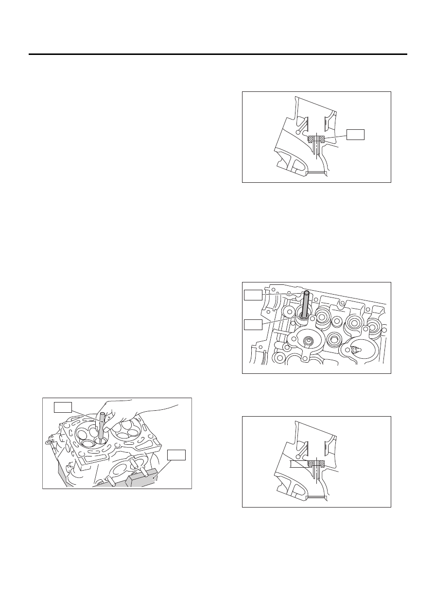
(1) Place the cylinder head on ST1 with the
combustion chamber upward so that valve
guides enter the holes in ST1.
(2) Insert the ST2 into valve guide and press it
down to remove the valve guide.
ST1
498267600
CYLINDER HEAD TABLE
ST2
499767200
VALVE GUIDE REMOVER
(3) Turn the cylinder head upside down and
place ST as shown in the figure.
ST
18251AA020
VALVE GUIDE ADJUSTER
(4) Before installing a new valve guide, make
sure that neither scratches nor damages exist
on the inside surface of the valve guide holes in
cylinder head.
(5) Put a new valve guide, coated with sufficient
oil, in cylinder, and insert ST1 into valve guide.
Press in until the valve guide upper end is flush
with the upper surface of ST2.
ST1
499767200
VALVE GUIDE REMOVER
ST2
18251AA020 VALVE GUIDE ADJUSTER
(6) Check the valve guide protrusion.
Valve guide protrusion: L
15.8 — 16.2 mm (0.622 — 0.638 in)
ME-00128
ST1
ST2
ME-00129
ST
ST1
ST2
ME-00130
ME-00632
L
ME(H4DOSTC)-67
MECHANICAL
CYLINDER HEAD ASSEMBLY
(7) Ream the inside of valve guide with ST.
Gently rotate the reamer clockwise while press-
ing it lightly into the valve guide, and return it
also rotating clockwise. After reaming, clean the
valve guide to remove chips.
ST
499767400
VALVE GUIDE REAMER
NOTE:
• Apply engine oil to the reamer when reaming.
• If the inner surface of the valve guide is torn, the
edge of the reamer should be slightly ground with
an oil stone.
• If the inner surface of the valve guide becomes
lustrous and the reamer does not chips, use a new
reamer or remedy the reamer.
(8) Recheck the contact condition between
valve and valve seat after replacing the valve
guide.
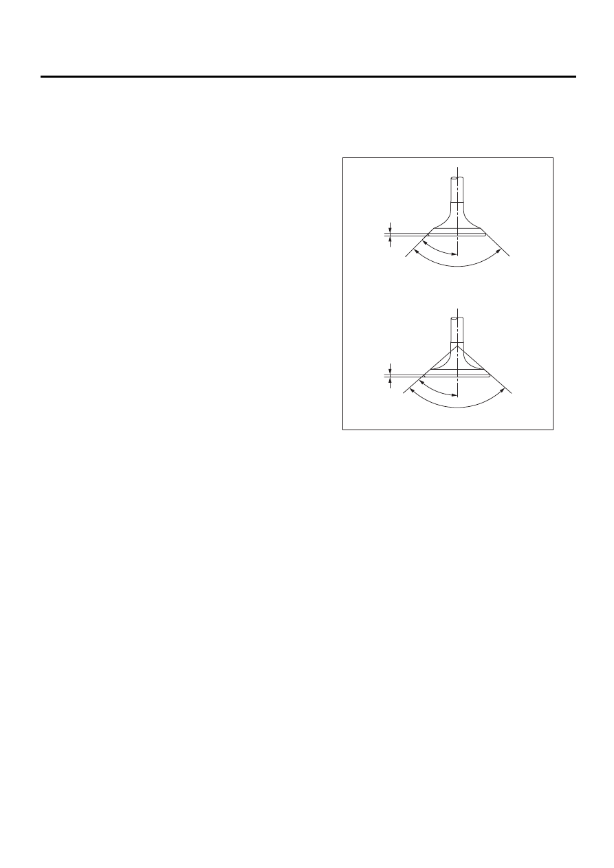
4. INTAKE AND EXHAUST VALVE
1) Inspect the flange and stem of valve, and re-
place if damaged, worn, or deformed, or if “H” is
less than the specified limit.
H:
Intake
Standard
1.2 mm (0.047 in)
Limit
0.8 mm (0.031 in)
Exhaust
Standard
1.5 mm (0.059 in)
Limit
0.8 mm (0.031 in)
Valve overall length:
Intake
104.4 mm (4.110 in)
Exhaust
104.7 mm (4.122 in)
2) Put a small amount of grinding compound on the
seat surface and lap the valve and seat surface. In-
stall a new intake valve oil seal after lapping.
ME-00131
90˚
+1
-0
H
H
45˚
90˚
+1
-0
45˚
Нет комментариевНе стесняйтесь поделиться с нами вашим ценным мнением.
Текст